Kramer Electronics, Ltd.
Contents Contents 1 2 2.1 3 3.1 Introduction Getting Started Quick Start Overview About the VP-23RC 1 1 1 3 3 3.1.1 3.1.2 3.1.3 Understanding the Presentation Switcher Section Understanding the Media / Room Controller Section Controlling the VP-23RC 3 4 5 3.2 3.3 3.4 4 4.1 4.2 4.3 5 6 6.1 6.2 6.3 7 7.
Contents 9.3.4 Turning the Light of the Backlit Buttons On and Off 34 9.4 The Presentation Switcher Section Operation 34 9.4.1 9.4.2 9.4.3 The Independent Switchers Mode The Master Audio Mode The Presentation Switcher SELECTOR Buttons Macro Sequence 34 35 37 10 10.1 Flash Memory Upgrade Flash Memory Upgrade for the Presentation Switcher Section 38 38 10.1.1 Downloading from the Internet 10.1.2 Connecting the PC to the RS-232 Port 10.1.3 Upgrading the Firmware 38 38 39 10.
Contents Figure 24: Atmel – Flip Window Figure 25: Device Selection Window Figure 26: Selecting the Device from the Selection Window Figure 27: Loading the Hex Figure 28: RS-232 Window Figure 29: Atmel – Flip Window (Connected) Figure 30: Atmel – Flip Window (Operation Completed) Figure 31: The KFR-Programmer Window 39 40 40 41 41 42 42 44 Tables Table 1: Terminology Used in this User Manual Table 2: Front Panel VP-23RC Presentation Switcher / Controller Features Table 3: Rear Panel VP-23RC Presentation S
Introduction 1 Introduction Welcome to Kramer Electronics! Since 1981, Kramer Electronics has been providing a world of unique, creative, and affordable solutions to the vast range of problems that confront the video, audio, presentation, and broadcasting professional on a daily basis. In recent years, we have redesigned and upgraded most of our line, making the best even better! Our 1,000-plus different models now appear in 11 groups1 that are clearly defined by function.
Getting Started 2 KRAMER: SIMPLE CREATIVE TECHNOLOGY
Overview 3 Overview This section describes: Using shielded twisted pair (STP)/unshielded twisted pair (UTP) (see section 6.3) The VP-23RC (see section 3.1) Presentation Switcher section (see section 3.1.1) Media / Room Controller (see section 3.1.2) Means of control (see section 3.1.3) An example of how to connect the VP-23RC (see section 3.2) Recommendations for achieving the best performance (see section 3.3) Terminology used in this user manual (see section 3.4) 3.
Overview Digital microphone input level control and digital master audio level control Microphone talk-over mode1 A CAT 5 output, with a transmission range of more than 300 feet (over 100 meters) that transmits VGA/UXGA signals2 to a remote acceptor via a receiver An internal 5-Watt per channel (24kHz, 3dB) power amplifier for connecting the speakers directly to the machine A panel LOCK button to prevent tampering with the front panel Recall of the previous setup from non-volatile memory Audio output level
Overview 3.1.3 Controlling the VP-23RC Control the VP-23RC using the front panel buttons, or remotely via: RS-2321 serial commands transmitted by a touch screen system, PC, or other serial controller The Kramer Infrared remote control transmitter The ETHERNET2 The VP-23RC is dependable, rugged, and fits into two vertical spaces (2U) of a standard 19” professional rack.
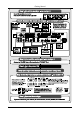
Overview 3.2 Connecting the VP-23RC Rear Panel The VP-23RC can be connected in different configurations, integrating the Presentation Switcher section with the Media/Room Controller section.
Overview To connect the VP-23RC as illustrated in the block diagram in Figure 1: Connect the A/V equipment1 to the Presentation Switcher section (see section 6) Connect the A/V equipment and room items to the Media/Room Controller section (see section 7) 3.
Your Presentation Switcher / Controller 4 Your Presentation Switcher / Controller The VP-23RC front and rear panels relate in the following way: The Presentation Switcher section relates to the AUDIO, VIDEO and SWITCHER CONTROL areas on the rear panel The Media/Room Controller section relates to the CONTROLLER area on the rear panel The Power connector, the RS-232 port in the SWITCHER CONTROL AREA and the ETHERNET port are common to both sections This section describes the VP-23RC: Front panel (see secti
Your Presentation Switcher / Controller Figure 2: VP-23RC Presentation Switcher / Controller – Front View 9
Your Presentation Switcher / Controller Table 2: Front Panel VP-23RC Presentation Switcher / Controller Features # 1 Feature IR (Infrared) Receiver 2 3 4 POWER Switch IR IN Receiver MEDIA / ROOM CONTROLLER Buttons s-VIDEO (Y/C)-AUDIO SELECTOR Buttons VIDEO (CV)-AUDIO SELECTOR Buttons VGA/UXGA-AUDIO SELECTOR Buttons CV Button 5 6 7 8 9 10 11 12 13 14 Function Signals from the Kramer remote control transmitter illuminate the LED Illuminated switch for turning the unit ON or OFF 1 Accepts IR remote comma
Your Presentation Switcher / Controller Figure 3: VP-23RC Presentation Switcher / Controller – Rear View 11
Your Presentation Switcher / Controller Table 3: Rear Panel VP-23RC Presentation Switcher / Controller Features Feature MIC IN Connector COND.
Your Presentation Switcher / Controller 4.3 The VP-23RC Underside Panel Figure 4 and Table 4 define the VP-23RC underside features: RESET VS HS Figure 4: VP-23RC Presentation Switcher / Controller – Underside View Table 4: VP-23RC Underside Panel Features Feature RESET Button VS Switch HS Switch Function Press to reset the unit prior to firmware upgrade (see section 10.
Installing the VP-23RC on a Rack 5 Installing the VP-23RC on a Rack This section describes what to do before installing on a rack and how to rack mount.
Connecting the VP-23RC Presentation Switcher Section 6 Connecting the VP-23RC Presentation Switcher Section To connect1 the VP-23RC Presentation Switcher section, as illustrated in the example in Figure 5, do the following2: 1.
Connecting the VP-23RC Presentation Switcher Section 8. If required, connect a PC to the RS-232 port (see section 8.1.1).
Connecting the VP-23RC Presentation Switcher Section 6.
Connecting the VP-23RC Presentation Switcher Section 6.
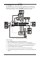
Connecting to the Media / Room Controller Equipment 7 Connecting to the Media / Room Controller Equipment To connect1 the VP-23RC Media/Room Controller section, as the example illustrated in Figure 10 shows, do the following2: 1. Connect the RELAY3 terminal block connectors as follows: Connect RELAY 1 to the blinds Connect RELAY 2 to the lighting system Connect RELAY 3 to the projector lift Connect RELAY 4 to the screen 2.
Connecting to the Media / Room Controller Equipment s-Video Player Screen Blinds Composite Video Player Computer Graphics Source Projector Projector Lift Lighting System Figure 10: Connecting the VP-23RC Media/Room Controller Section 20 KRAMER: SIMPLE CREATIVE TECHNOLOGY
Connecting to the Media / Room Controller Equipment 7.1 Setting the Media / Room Controller PROGRAM Dipswitches The PROGRAM dipswitches are located in the CONTROLLER area of the rear panel (see section 7.1). Table 6 defines the PROGRAM dipswitch settings: Table 6: PROGRAM Dipswitch Settings DIPS 7.1.1 1 Description ON for Firmware Upgrade (see section 10.2) 2 Not used 3 ON for Factory Reset (see section 7.1.
Controlling the VP-23RC 8 Controlling the VP-23RC The VP-23RC can be controlled via: A PC (see section 8.1) RS-232 and RS-485 (see section 8.2) The ETHERNET (see section 8.3) 8.1 Controlling the VP-23RC via a PC To control the VP-23RC1 via the control software: 1. Connect your PC to the SWITCHER CONTROL RS-232 port on the rear panel (see section 8.1.1). 2. Download the Windows®-based Kramer control software (provided with the machine) to your PC. 3. Run the application. The Port window appears. 4.
Controlling the VP-23RC 8.1.1 Connecting an RS-232 port to a PC You can connect a PC to the VP-23RC via an RS-232 port, as defined in Table 7: Table 7: Connecting an RS-232 Port to a PC RS-232 Rear Panel Port Location Port 1 in the CONTROLLER area RS-232 port in the SWITCHER CONTROL area For… Media/Room Controller firmware upgrade (see section 10.2) Presentation Switcher firmware upgrade (see section 10.
Controlling the VP-23RC 8.2 Controlling Additional Kramer Machines via RS-232 and RS-485 You can cascade other Kramer machines1 together with the VP-23RC via the RS-485 port, and control them via the SWITCHER CONTROL RS-232 port using a PC. To connect two Kramer VP-8x8A machines to the VP-23RC, via RS-485, as illustrated in the example in Figure 13, do the following: 1.
Controlling the VP-23RC VP-23RC Machine # 2 Machine # 3 VP-8x8A VP-8x8A Figure 13: Control Configuration via RS-232 and RS-485 8.3 Controlling via the ETHERNET You can control the VP-23RC via the Ethernet as well as configure the Media/Room Controller buttons and the Presentation Switcher SELECTOR buttons1. 1 Done by the system integrator, see section 9.
Controlling the VP-23RC Before using the VP-23RC via a network hub or network router, make sure that: The IP number of the machine is defined on the network subnet and that its number is unique in the local network A Firewall is not preventing access to the device If you need further assistance, contact your system integrator. 8.3.
Controlling the VP-23RC 6. Select Use the following IP Address, and fill in the details as shown in Figure 15. 7. Click OK. Figure 15: Internet Protocol (TCP/IP) Properties Window Remember to restore your previous PC settings after setting the VP-23RC IP If the Media/Room Controller is not yet configured you can control via the Ethernet, the Presentation Switcher section only. 8.3.
Operating Your VP-23RC 9 Operating Your VP-23RC This section describes the: Front panel buttons (see section 9.1) VP-23RC button configuration (see section 9.2) Media/Room Control section operation (see section 9.3) Presentation Switcher section operation (see section 9.4) 9.
Operating Your VP-23RC Pressing an illuminated AUDIO SELECTOR button for more than 2 seconds disconnects that master audio output, and the button no longer illuminates. The video will continue to display but without sound.
Operating Your VP-23RC Projector Lift Projector Blinds s-Video Player INTERNET Screen Lighting System Composite Video Player Figure 16: Example of a Typical Media/Room Controller Section Configuration Table 9: Connection Scheme (for the example in Figure 16) This connector: RELAY 1 RELAY 2 RELAY 3 RELAY 4 1 IR 1 PIN IR 2 PIN1 IR 3 PIN RS-232 Terminal Block Connector (1 and 2) Ethernet Controls: The blinds The lighting system Projector lift motor The screen settings motor A composite video player An s-V
Operating Your VP-23RC Figure 17 shows a common setup for the VP-23RC in a media room. An overhead projector and screen, speakers, lights; and a cabinet with a DVD and a VCR inside, are all controlled via the VP-23RC. The presenter’s laptop is located on the podium (also connected to the VP-23RC), alongside the VP-23RC.
Operating Your VP-23RC 9.3.1 Operating the Media / Room Controller In the following example1, illustrated in Figure 18, the VP-23RC is labeled2 with specific functions and each button is programmed3 to perform several tasks4 as defined in Table 10. Each button may be assigned with up to 15 commands.
Operating Your VP-23RC 9.3.2 An Example of Operating the VP-23RC Figure 19 shows an operating example: VCR DVD ON DVD Vol UP Vol DOWN PC VCR PC OFF Figure 19: VP-23RC Operation Example 9.3.3 Using the Media / Room Controller Macro Buttons Pressing any button initiates a macro sequence1, during which the button blinks (as programmed by the system integrator).
Operating Your VP-23RC If you want to stop a macro sequence, press and hold that button for 5 seconds. The sequence will come to an end. You can resume operation by pressing any button1. The unit will carry out the macro sequence commands from the beginning. 9.3.4 Turning the Light of the Backlit Buttons On and Off When the room is darkened, the buttons can be illuminated for convenience.
Operating Your VP-23RC Each pressed button illuminates1, indicating selection and outputting of that video and audio source. If a button includes a macro sequence, it will be executed when pressing that button. UXGA Acceptor UXGA Sources CV Video Sources s-Video Sources CV Video Acceptor s-Video Acceptor Speakers Figure 20: Separate Switcher Mode 9.4.
Operating Your VP-23RC (I) When pressing button 2 under the VGA/UXGA-AUDIO SELECTOR, the UXGA IN 2 signal is routed to the display1. The VGA/UXGA button under the MASTER AUDIO SELECTOR section automatically illuminates, and the UXGA audio signal is routed to the SPKR OUT2 and the MASTER OUT2 terminal block connectors simultaneously3.
Operating Your VP-23RC 9.4.3 The Presentation Switcher SELECTOR Buttons Macro Sequence The SELECTOR buttons can be configured to execute a sequence of commands (a macro) in a similar way to the Media / Room Controller buttons (see section 9.3.1) so that when a SELECTOR button is pressed, it will first perform the switching action and concurrently carry out the macro. The example in Figure 22 illustrates a macro sequence that can be programmed to a Presentation Switcher SELECTOR button.
Flash Memory Upgrade 10 Flash Memory Upgrade The firmware is upgraded separately for the Presentation Switcher section (see section 10.1) and for the Media/Room Controller section (see section 10.2). 10.1 Flash Memory Upgrade for the Presentation Switcher Section The VP-23RC firmware for the Presentation Switcher section is located in FLASH memory, which lets you upgrade to the latest Kramer firmware version in minutes! The process involves: Downloading from the Internet (see section 10.1.
Flash Memory Upgrade 10.1.3 Upgrading the Firmware Follow these steps to upgrade the firmware for the Presentation Switcher section: 1. Double click the desktop icon: “ Shortcut to FLIP.EXE”. The Splash screen appears as follows: Figure 23: Splash Screen 2. After a few seconds, the Splash screen is replaced by the “ Atmel –Flip” window: Figure 24: Atmel – Flip Window 3.
Flash Memory Upgrade Figure 25: Device Selection Window 4. Click the button next to the name of the device and select from the list: AT89C51RD2: AT89C51RD2 T89C51RD2 Figure 26: Selecting the Device from the Selection Window 5. Click OK and select “ Load Hex” from the File menu.
Flash Memory Upgrade A Figure 27: Loading the Hex 6. The Open File window opens. Select the correct HEX file that contains the updated version of the firmware for VP-23RC (for example, 23RCM_V1p2.hex) and click Open. 7. Press the keyboard shortcut key F3 (or select the “ Communication / RS232” command from the Settings menu, or press the keys: Alt SCR). The “ RS232” window appears.
Flash Memory Upgrade A VP23RC.hex Figure 29: Atmel – Flip Window (Connected) 9. Click Run. After each stage of the operation is completed, the check-box for that stage becomes colored green1. When the operation is completed, all 4 check-boxes will be colored green and the status bar message: Memory Verify Pass appears2: A VP23RC.hex Figure 30: Atmel – Flip Window (Operation Completed) 10. Close the “ Atmel –Flip” window. 11. Disconnect the power on the VP-23RC.
Flash Memory Upgrade 12. Disconnect the RS-232 rear panel port on the VP-23RC unit from the Null-modem adapter. 13. Release the FLASH PROG button on rear panel. 14. Connect the power to the VP-23RC. 10.
Flash Memory Upgrade 10.2.3 Upgrading Firmware Follow these steps to upgrade the firmware: 1. Double click the KFR-Programmer desktop icon. The KFR-Programmer window appears (see Figure 31). Figure 31: The KFR-Programmer Window 2. Select the required COM Port1. 3. Press the File button to select the .s19 firmware file included in the package. 4. Press the Send button to download the file. The Send button lights red. 5. Wait until downloading is completed and the red Send button turns off. 6.
Flash Memory Upgrade 10.3 Troubleshooting Firmware Upgrade Issues If the RC device does not communicate and it is impossible to perform the flash upgrade procedure, the problem may sometimes be solved by performing the factory default restore procedure. To restore the factory default settings, do the following: 1. Turn off the VP-23RC unit. 2. In the CONTROLLER area of the rear panel, set DIP-switch 3 ON for factory reset. 3. Turn on the machine. 4.
Technical Specifications 11 Technical Specifications Table 11 includes the technical specifications1: Table 11: Technical Specifications of the VP-23RC Presentation Switcher / Controller PORTS (CONTROLLER): INPUTS: OUTPUTS: MAX. OUTPUT LEVEL: BANDWIDTH (-3dB): DIFF. GAIN: DIFF.
Hex Table 12 Hex Table Table 12 lists the Hex values (which the protocol in section 13 describes in more detail) for the VP-23RC Presentation Switcher section: Table 12: VP-23RC Hex Table Inputs VGA s-Video Composite Video Group # In 1 In 2 In 3 In 4 In 1 In 2 In 3 In 4 In 1 In 2 In 3 In 4 Composite Video OUT and Audio OUT CV 01 81 81 81 01 82 81 81 01 83 81 81 01 84 81 81 s-Video OUT and Audio OUT s-Video VGA OUT and Audio OUT VGA 01 81 82 81 01 82 82 81 01 83 82 81 01 84 82 81 01 81 83 81 01 82
Hex Table Table 16: Set the Audio Output Gain Control for the Master Audio Audio Gain Control for Master Out 16 85 80 81 Mute 16 85 F9 81 … … 0dB 16 85 FF 81 3dB Table 17: Increase or Decrease the Audio Output Gain by One Step Increase Composite Video 18 81 80 81 18 82 80 81 18 83 80 81 18 84 80 81 18 85 80 81 Decrease 18 81 81 81 18 82 81 81 18 83 81 81 18 84 81 81 18 85 81 81 48 s-Video VGA Microphone Master Out KRAMER: SIMPLE CREATIVE TECHNOLOGY
Communication Protocol 13 Communication Protocol This protocol, which enables RS-232 communication between the VP-23RC and the PC, uses 4 bytes of information, and data is at 9600 baud, no parity, 8 data bits and 1 stop bit.
Communication Protocol Table 19: Instruction Codes # INSTRUCTION DESCRIPTION DEFINITION FOR SPECIFIC INSTRUCTION INPUT OUTPUT 0 1 RESET MACHINE SWITCH GROUPS 2 SWITCH AUDIO OUTPUTS 5 REQUEST GROUP STATUS 6 REQUEST STATUS OF MASTER AUDIO OUTPUT BREAKAWAY SETTING 0 REQUEST BREAKAWAY SETTING ERROR 0 8 11 16 18 22 25 RESET MACHINE SET AUDIO GAIN OF AUDIO OUTPUT INCREASE/DECREASE AUDIO GAIN REQUEST GAIN 30 LOCK FRONT PANEL 31 57 REQUEST WHETHER PANEL IS LOCKED MEDIA CONTROL REQUEST MEDIA CON
Communication Protocol NOTE 3 The reply to a “ REQUEST” instruction is as follows: the same instruction and input codes as were sent are returned, and the OUTPUT is assigned to the value of the requested parameter.
LIMITED WARRANTY Kramer Electronics (hereafter Kramer) warrants this product free from defects in material and workmanship under the following terms. HOW LONG IS THE WARRANTY Labor and parts are warranted for seven years from the date of the first customer purchase. WHO IS PROTECTED? Only the first purchase customer may enforce this warranty. WHAT IS COVERED AND WHAT IS NOT COVERED Except as below, this warranty covers all defects in material or workmanship in this product.
For the latest information on our products and a list of Kramer distributors, visit our Web site: www.kramerelectronics.com, where updates to this user manual may be found. We welcome your questions, comments and feedback. Safety Warning: Disconnect the unit from the power supply before opening/servicing. Caution Kramer Electronics, Ltd. Web site: www.kramerelectronics.com E-mail: info@kramerel.