
User's Manual


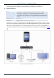
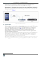
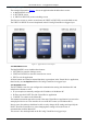
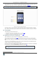
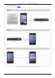
Table Of Contents
KRAMER: SIMPLE CREATIVE TECHNOLOGY
The Virtual Device – an Application Example
4
3.3.1 A Setup Example
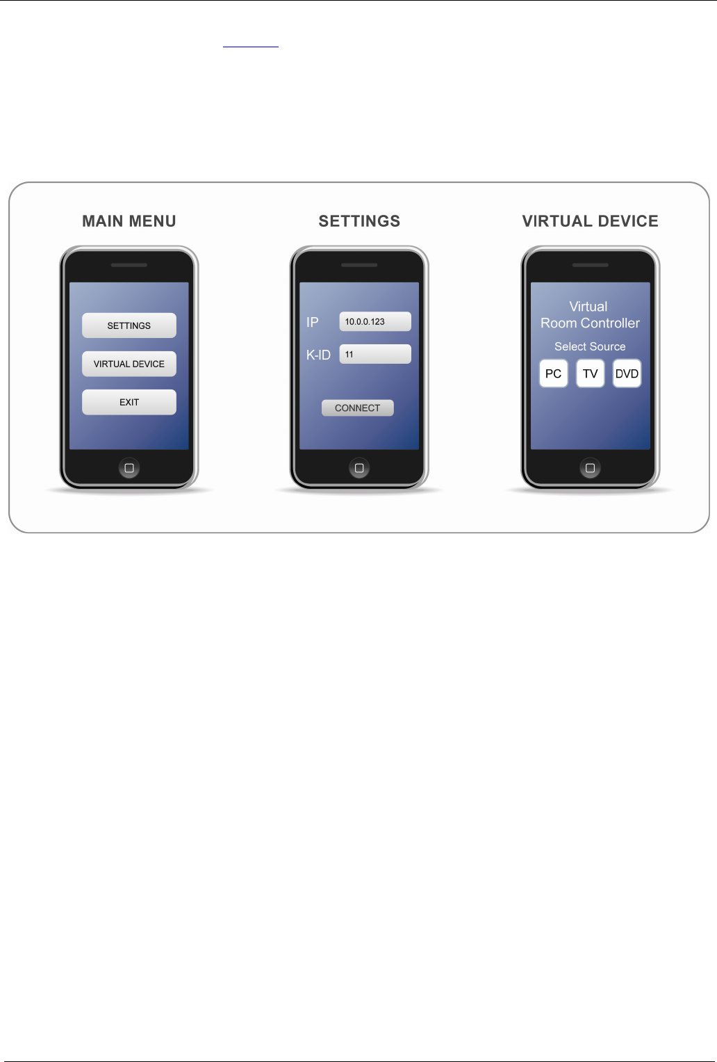
The example illustrated in Figure 3, shows an application that includes three screens:
• A MAIN MENU screen
• A SETTINGS screen
• A VIRTUAL DEVICE (source switching) screen
The first two screens are used to set and enter the VIRTUAL DEVICE screen (the third screen).
The VIRTUAL DEVICE screen is duplicated in the K-Config Virtual Device triggers layer.
Figure 3: Application Screen Examples
The MAIN MENU Screen
The MAIN MENU screen includes three buttons:
• SETTINGS to enter the Settings screen
• VIRTUAL DEVICE to enter the virtual device screen
• EXIT to exit the application
All three buttons are related to internal functions or procedures in the Virtual Device application;
therefore they are not duplicated in the K-Config Virtual Device triggers layer.
The SETTINGS Screen
The SETTINGS screen lets you configure the communication setting with the Master RC and
includes three buttons as well:
• IP (as an option) to manually configure the IP Address of the Master RC
• K-ID to enter the K-NET ID of the Virtual Device application
• CONNECT to connect to the Master RC
This manual connection approach is useful if the same Virtual Device application is to run on the
same physical device as a user interface for several K-NET rooms (several Master RCs).
In most cases, the end-user should not be able to easily change the IP settings and especially the
K-NET ID of the Virtual Devices, since changing these settings will result in loss of
communication with the Master RC.
This screen is also not duplicated on the K-Config Virtual Device triggers layer.