Kramer Electronics, Ltd. Kramer Control Systems Virtual Device Build Guidelines Revision 1 Intended for Kramer Technical Personnel or external System Integrators. To check that you have the latest version, go to the DOWNLOADS section of our Web site at: http://www.kramerelectronics.com/support/downloads.
Contents Contents 1 1.1 2 3 3.1 3.2 3.3 3.3.1 3.4 3.4.1 3.4.2 4 4.1 4.1.1 4.1.2 4.2 4.3 4.4 4.
Introduction 1 Introduction Kramer Electronics offers a wide variety of control products that meet numerous different AV requirements. These solutions make up the Kramer control system and offer seamless compatibility with Kramer signal management and scaling products, as well as interfacing with display devices and other third party products for complete room control solutions.
The Virtual Device – an Application Example 3 The Virtual Device – an Application Example The following sections define the general guidelines for building a Virtual Device. 3.
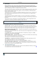
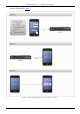
The Virtual Device – an Application Example 3.2 Hardware Setup UDP 1 connection is used through port 50000 for connecting between the Mobile Device (iPhone/iPad®/Android) and the Kramer Master RC (SV-552 in this example). Both the Master RC and the Mobile Device should use the same net/sub-net range.
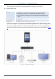
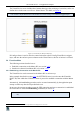
The Virtual Device – an Application Example 3.3.1 A Setup Example The example illustrated in Figure 3, shows an application that includes three screens: • A MAIN MENU screen • A SETTINGS screen • A VIRTUAL DEVICE (source switching) screen The first two screens are used to set and enter the VIRTUAL DEVICE screen (the third screen). The VIRTUAL DEVICE screen is duplicated in the K-Config Virtual Device triggers layer.
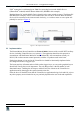
The Virtual Device – an Application Example The VIRTUAL DEVICE Screen The Virtual Device screen includes three buttons that trigger the switching of a switcher, scaler or a similar device in the room 1 as well as a “Select Source” text label, see Figure 4. This screen is duplicated as the Virtual Device in the K-Config Virtual Device triggers layer.
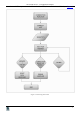
The Virtual Device – an Application Example The Virtual Device application then waits for a response from the Master RC for a predefined time period, as illustrated in Figure 5: Figure 5: Connecting the Virtual Device to the Room Controller 6 KRAMER: SIMPLE CREATIVE TECHNOLOGY
The Virtual Device – an Application Example Once an "OK" response is received from the Master RC, the connection is established, see Figure 6 Figure 6: Connecting Flow Chart 7
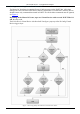
The Virtual Device – an Application Example 3.4.2 Sending and receiving Data to/from Master RC The Master RC broadcasts its outgoing Protocol 3000 messages on the K-NET bus. All its data messages are sent to all the K-NET devices that are connected to it. Each K-NET Auxiliary Device should execute only commands that match its K-NET ID. All the Other commands must be ignored, see Figure 8. Depending on the Master RC in use, up to two Virtual Devices with reserved K-NET ID of 11 and 12 can be used.
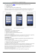
The Virtual Device – an Application Example The number of buttons on the Virtual Device and their functionalities are defined using the K-Config software in K-Config Virtual Device triggers layer. Pressing a "button" on a Virtual Device application will send a corresponding command to the Master RC.
The Virtual Device – an Application Example Figure 8: Sending and Receiving Commands Important – The Master RC can send mostly button status/lighting and text field commands to its KNet Aux devices. However, the competent developer can easily use a combination of virtual buttons defined as a property of the Virtual Device in K-Config and use these messages as global variables and other powerful options to enable application flexibility.
Communication Protocol 3000 4 Communication Protocol 3000 = Carriage return (ASCII 13 = 0x0D) = Line feed (ASCII 10 = 0x0A) = Space (ASCII 32 = 0x20) 4.1 Host message format start # Address (optional) body Destination_id@ message delimiter 4.1.1 Simple command (Commands string with only one command without addressing): start # body Command SP Parameter_1,Parameter_2,… delimiter Device message format: start ~ Address (optional) Sender_id@ body message delimiter 4.1.
Communication Protocol 3000 4.3 Commands Entering If a terminal software is used to connect over serial \ ethernet \ USB port, it is possible to directly enter all commands characters ( will be entered by Enter key, that key sends also , but this char will be ignored by commands parser). Sending commands from 3rd party controllers requires the coding of some characters in a special form (such as \X##).
Communication Protocol 3000 BTN - Button ID according to the configuration in K-Config RED, GREEN, BLUE- Color intensity for each base color. Values are from 0 (No color) to 255 (Full color). Plain buttons that support only on/off light should ignore values of these parameters (except if all set to zero – same as turning light off). STATE : "0" or "Off" (Color parameters can be ignored). "1" or "On" "2" or "Slow" for slow blink "3" or "Fast" for fast blink RESULT – OK if command has been executed.
Communication Protocol 3000 Result codes (errors) Syntax No error. Command running succeeded ~DEV_ID@COMMAND PARAMETERS OKCRLF Protocol Errors Syntax Error (For example: Not enough parameters) ~DEV_ID@COMMAND ERR001CRLF Command not available for this device ~DEV_ID@ ERR002CRLF Parameter is out of range ~DEV_ID@COMMAND ERR003CRLF Unauthorized access (running command without the matching login).