Kramer Electronics, Ltd.
Contents Contents 1 2 2.1 3 4 5 5.1 5.1.1 Introduction Getting Started Quick Start Overview Your Presentation Switcher / Scaler Installing on a Rack Before Installing on a Rack CAUTION!! 1 1 2 3 5 12 12 12 5.2 6 6.1 7 7.1 7.2 Instructions for Rack-Mounting Connecting your Presentation Switcher / Scaler Connecting a PC Presentation Switcher / Scaler Buttons Switching an Input The PIP Button Feature 12 13 15 16 16 17 7.3 7.4 8 8.1 8.2 8.3 8.
Contents 8.5.7.1 8.5.8 8.5.9 8.5.9.1 8.
Contents Figure 39: OSD Output Status Figure 40: Output Setting User Mode Setting Utility Screen Figure 41: Factory Reset Utility Screen Figure 42: Advanced Utility Screen Figure 43: Non-standard Resolution in the Information Screen Figure 44: Information Screen 37 38 39 39 41 41 Tables Table 1: Front Panel Presentation Switcher / Scaler Features Table 2: Rear Panel Presentation Switcher / Scaler Features Table 3: Recommended Ambient Temperature and Humidity Range Table 4: PIP Source Appearance Availabili
Introduction 1 Introduction Welcome to Kramer Electronics (since 1981): a world of unique, creative and affordable solutions to the infinite range of problems that confront the video, audio and presentation professional on a daily basis. In recent years, we have redesigned and upgraded most of our line, making the best even better! Our 350-plus different models now appear in 8 Groups1, which are clearly defined by function.
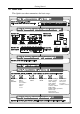
Getting Started 2.1 Quick Start This Quick start chart summarizes the basic steps.
Overview 3 Overview The VP-719xl/VP-720xl/VP-723xl /VP-724xl is a Presentation Switcher / Scaler designed for a wide variety of presentation and multimedia applications. It is a true multi-standard video to RGBHV (pixel) scaler and a seamless presentation switcher. It converts video, s-Video, component video, VGA-through-UXGA and DVI signals to a range of user-selectable VESA and HDTV pixel rates, as well as some other special resolutions.
Overview Switches the audio channels in audio-follow-video mode Includes an OSD (On-Screen Display) – for making adjustments – that can be located anywhere on the screen, and can be doubled in size For example, the OSD can be used to deactivate the source prompt, choose the color of the blank screen, and choose from three seamless switching image transition speeds Includes seven1 multi-functional INPUT SELECTOR buttons that can cycle between selecting a source, freezing that source, or deactivating that so
Your Presentation Switcher / Scaler To achieve the best performance: Connect only good quality connection cables, thus avoiding interference, deterioration in signal quality due to poor matching, and elevated noise- levels (often associated with low quality cables) Avoid interference from neighboring electrical appliances and position your Kramer VP-719xl/VP-720xl/VP-724xl away from moisture, excessive sunlight and dust 4 Your Presentation Switcher / Scaler This section defines each of the Presentation S
Your Presentation Switcher / Scaler Figure 1: VP-719xl Presentation Switcher / Scaler Front Panel1 Figure 2: VP-719xl Presentation Switcher / Scaler Rear Panel2 1 Items 10 and 11, which appear in Table 1 are not included in this machine 2 Items 10 and 15, which appear in Table 2 are not included in this machine 6 KRAMER: SIMPLE CREATIVE TECHNOLOGY
Your Presentation Switcher / Scaler VGA Figure 3: VP-720xl Presentation Switcher / Scaler Front Panel1 Figure 4: VP-720xl Presentation Switcher / Scaler Rear Panel2 1 Item 10, which appears in Table 1 is not included in this machine 2 Items 10 and 15, which appear in Table 2 are not included in this machine 7
Your Presentation Switcher / Scaler VGA Figure 5: VP-723xl Presentation Switcher / Scaler Front Panel1 Figure 6: VP-723xl Presentation Switcher / Scaler Rear Panel2 1 Item 10, which appears in Table 1 is not included in this machine 2 Items 10 and 15, which appear in Table 2 are not included in this machine 8 KRAMER: SIMPLE CREATIVE TECHNOLOGY
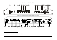
Your Presentation Switcher / Scaler Figure 7: VP-724xl Presentation Switcher / Scaler Front Panel Figure 8: VP-724xl Presentation Switcher / Scaler Rear Panel 9
Your Presentation Switcher / Scaler Table 1: Front Panel Presentation Switcher / Scaler Features 6 7 8 9 10 Feature POWER Switch IR Receiver / LED AV1 AV2 YC1 INPUT SELECTOR 1 Buttons # 1 2 3 4 5 YC2 COMPONENT DVI 2 VGA 1 2 VGA 2 3 11 12 13 PIP Button BLANK Button MUTE Button 14 15 16 17 18 19 20 21 FREEZE Button MENU Button ENTER Button - Button DOWN Button UP Button + Button RESET TO VGA Button 22 PANEL LOCK Button Function Illuminated switch for turning the machine ON or OFF Red when the unit
Your Presentation Switcher / Scaler Table 2: Rear Panel Presentation Switcher / Scaler Features Feature VIDEO OUT 1 HD15 Connector Function Connects to the video acceptor (for example, a plasma display, projector or monitor) that displays the scaled output In the default HDTV mode, the signal goes out via 3 PINS: PIN 1 is Pr, PIN 2 is Y, PIN 3 is Pb 2 VIDEO OUT 2 HD15 Connector Connects to the video acceptor (for example, a plasma display, projector or monitor) that displays the scaled output In the def
Installing on a Rack 5 Installing on a Rack This section describes what to do before installing the Presentation Switcher / Scaler on a rack (see section 5.1) and how to install on a rack (see section 5.2). 5.
Connecting your Presentation Switcher / Scaler 6 Connecting your Presentation Switcher / Scaler To connect the VP-724xl for example1 (see Figure 9), do the following2: 1.
Connecting your Presentation Switcher / Scaler 4. Connect the LINE AUDIO OUT terminal block connector to one of the audio acceptors, for example, speakers (not illustrated in Figure 9) 5. Connect the SPKR OUT terminal block to a pair of loud speakers. 6. The power cord1 (the power connector is not illustrated in Figure 9). 7. A PC (optional), as section 6.1 describes.
Connecting your Presentation Switcher / Scaler 6.1 Connecting a PC You can connect a PC (or other controller) to the VP-724xl via the RS-232 port for remote control, and for upgrading the firmware.
Presentation Switcher / Scaler Buttons 7 Presentation Switcher / Scaler Buttons The VP-724xl includes the following front panel buttons: 8 INPUT SELECTOR buttons1, see section 7.1 A PIP button2, see section 7.2 BLANK, MUTE and FREEZE buttons 6 OSD buttons A RESET TO VGA button A PANEL LOCK button, see section 7.3 7.1 Switching an Input Each INPUT SELECTOR button can be used to select the source. It can also be programmed to freeze the image or display a blank screen when pressed again.
Presentation Switcher / Scaler Buttons 7.2 The PIP Button Feature The Picture-in-Picture inserter (PIP) is used to present video and graphic sources simultaneously. You can display: An inserted video source1 PIP over a graphic source2 display An inserted graphic source2 PIP over a video source1 display 7.2.1 Selecting the PIP Source To use the PIP feature, set the PIP source via the OSD menu by using either the OSD front-panel buttons or the remote-transmitter keys.
Presentation Switcher / Scaler Buttons When selecting one PIP source, your Presentation Switcher / Scaler automatically recognizes and displays the selected graphic PIP source on all the video displays1 and the selected video source on all the graphic1 displays, compliant to Table 4.
Presentation Switcher / Scaler Buttons 7.2.4 Toggling between the PIP and the Screen Source (SWAP) To toggle back and forth between the PIP Source and the main display, do the following: Press the SWAP key on the infra-red remote control transmitter (see Figure 16). The OSD SWAP status appears superimposed over the top right corner of the screen for a few seconds1 only when the Source Prompt is ON, as Figure 13 illustrates.
Presentation Switcher / Scaler Buttons PIP Auto(NTSC VGA-2 System) Source: Figure 14: PIP Size – Split Screen 7.2.5.2 Moving the Position of the PIP To move the position of the PIP, as illustrated in Figure 15, use the OSD menu (Utility>>PIP Setting>>H-Position; V-Position). When the Source Prompt is ON, and the PIP Frame is ON, you can instantly position the PIP using the preset position control keys on the infra-red remote control transmitter.
Presentation Switcher / Scaler Buttons 7.3 Locking and Unlocking the Front Panel You can lock the front panel1 to safeguard the settings on the VP-724xl.
Presentation Switcher / Scaler Buttons Figure 16: Infra-Red Remote Control Transmitter 22 KRAMER: SIMPLE CREATIVE TECHNOLOGY
Presentation Switcher / Scaler Buttons Table 5: Infra-Red Remote Control Transmitter Functions Keys OUT FREEZE POWER 1 INPUT SELECTOR INFO. PRESET POSITION 2 CONTROL AUTO IMAGE MENU 7 NAVIGATION CONTROL AUTO GAIN 8 SWAP 9 PIP CONT. BRIGHT. AUDIO/ZOOM CONTROL7 MODE SCALE Function Selects the output resolution Pauses the output video Cycles power 8 separate keys for selecting each of the following sources: AV1, AV2, COMP.
Configuring the VP-724xl via the OSD MENU Screens 8 Configuring the VP-724xl via the OSD MENU Screens The OSD superimposes a menu on the screen from which you can configure and control each input signal on your VP-724xl, using the MENU, ENTER, , +, UP and DOWN OSD buttons on the front panel and the remote transmitter. To use the OSD menus: 1. Select the desired input signal. 2.
Configuring the VP-724xl via the OSD MENU Screens 8.1 Controlling the Brightness and Contrast Figure 19 and Table 6 define the Brightness and Contrast screen.
Configuring the VP-724xl via the OSD MENU Screens 8.2 Controlling the Gamma and Color Figure 20 and Table 7 define the Gamma and Color Screen.
Configuring the VP-724xl via the OSD MENU Screens 8.3 Selecting the Source Figure 21 illustrates the Source screen, displaying the active source1 (main screen). Scroll up and down to change the source (same as selecting an INPUT with the remote transmitter or via the INPUT SELECTOR buttons). Figure 21: Source Selection Screen 8.4 Controlling the Scale Geometry Figure 22 illustrates the main Geometry Screen, from which you can scale and zoom.
Configuring the VP-724xl via the OSD MENU Screens 8.4.1 Setting the Scale Features Figure 23 (for a graphic source), Figure 24 (for a video source) and Table 8 define the Scale feature on the main Geometry screen.
Configuring the VP-724xl via the OSD MENU Screens Table 8: Geometry Scale Functions Button Aspect Ratio 6 Non-Linear 8.4.
Configuring the VP-724xl via the OSD MENU Screens The zoom ratio and the zoom position are illustrated by a small rectangle inside a transparent pop-up OSD Enlarge status box that appears at the top right corner of the screen, as the example in Figure 26 illustrates: Enlarge x 400% Auto(NTSC Sys tem) Figure 26: OSD Enlarge Status When you change the zoom ratio or zoom position, the screen image is adjusted accordingly, and the change is reflected in the pop-up OSD Enlarge status box. 8.4.2.
Configuring the VP-724xl via the OSD MENU Screens 8.4.2.
Configuring the VP-724xl via the OSD MENU Screens 8.5 Configuring via the Utility Screens Figure 31 shows the Utility menu, from which you can define the machine settings. Figure 31: Utility Screen 8.5.1 Choosing the Graphic Utility Settings From the Graphic1 Setting Utility screen (see Figure 32), you can set the color format, position, Color, hue, sharpness, frequency and phase, as well as auto image and auto gain (described in Table 10).
Configuring the VP-724xl via the OSD MENU Screens Table 10: Graphic Setting Utility Screen Features Button Color Format H-Position Function Range Default Selecting the color format lets you select RGB or YUV1 colorspace.
Configuring the VP-724xl via the OSD MENU Screens 8.5.3 Choosing the Audio Utility Settings From the Audio Setting Utility screen (see Figure 34), you can set the volume, treble, bass, and choose between stereo and mono. Figure 34: Audio Setting Utility Screen Table 12: Audio Setting Utility Screen Features Button Volume Function Adjust the volume Range 0 to 32 Default 16 Treble Adjust treble 0 to 12 6 Bass Adjust bass 0 to 12 Stereo Select Stereo ON or OFF 8.5.
Configuring the VP-724xl via the OSD MENU Screens Table 13: PIP Setting Utility Screen Features Button PIP On/Off Function Activate or deactivate the PIP feature PIP Source Select the PIP source, as described in section 7.2.
Configuring the VP-724xl via the OSD MENU Screens 8.5.6 Choosing the OSD Utility Settings Figure 37 and Table 15 define the OSD Setting Utility screen.
Configuring the VP-724xl via the OSD MENU Screens 8.5.7 Choosing the Output Utility Settings Figure 38 and Table 16 define the Output Utility settings. From the Output Setting Utility screen, you can set the Resolution, Refresh Rate, and a user definable output mode (see Figure 40 and Table 17).
Configuring the VP-724xl via the OSD MENU Screens 8.5.7.1 The User Mode Setting Figure 40 and Table 17 define the User Mode Setting1.
Configuring the VP-724xl via the OSD MENU Screens 8.5.8 Choosing Factory Reset From the Factory Reset Utility screen (see Figure 41), you can reset your VP-724xl to its preset default setting: Figure 41: Factory Reset Utility Screen 8.5.9 Choosing Advanced Utility Settings Figure 42 and Table 18 define the Advanced Utility screen.
Configuring the VP-724xl via the OSD MENU Screens Table 19 describes the User Define Measure features. Table 19: User Define Measure Features H Total User Mode Setting Definitions Horizontal Total H Start Horizontal active start point H Active V Start Horizontal active region Vertical active start point V Active Vertical active region Ch. Pump Charge pump current Color Color format H Freq Horizontal Frequency V Freq Vertical Frequency Measure Mode Select between Default and User Define 8.
Configuring the VP-724xl via the OSD MENU Screens Non-standard Resolution Figure 43: Non-standard Resolution in the Information Screen 8.
Technical Specifications 9 Technical Specifications Table 20 includes the technical specifications: 1 Table 20: Technical Specifications of the Presentation Switchers / Scalers INPUTS: MAX. OUTPUT LEVEL: OUTPUTS: OUTPUT RESOLUTIONS: CONTROL: ADDITIONAL CONTROLS: POWER SOURCE: DIMENSIONS: WEIGHT: ACCESSORIES: 2 x CV 1 Vpp/75 on RCA connectors; 2 x Y/C (s-Video) 1 Vpp (Y), 0.
VP-724xl Communication Protocol 10 VP-724xl Communication Protocol Set and Get command: Set Command: Y Control_Type Function Param CR Reply: Z Control_Type Function Param CRDone>CR Get Command: Y Control_Type Function Param CR Reply: Z Control_Type Function Param CR Example: 1. "Y 1 17 0-127 CR" -> set Contrast value. (4th byte is between 0 and 127). "Z 1 17 0-127 CR>" --> Reply value "DoneCR" --> command setting success 2. "Y 4 21 0-17 CR" -> get current output resolution.
VP-724xl Communication Protocol Control Type 0 0 0 0 0 0 0 0 0 0 0 0 0 0 0 0 0 0 0 0 0 0 0 0 0 0 1: Set 2: Get 1: Set 2: Get 1: Set 2: Get 1: Set 2: Get 1: Set 2: Get 1: Set 2: Get 1: Set 2: Get 1: Set 2: Get 1: Set 2: Get 1: Set 2: Get 1: Set 2: Get 44 14 15 16 17 18 19 20 21 22 23 24 25 26 27 28 29 30 31 32 33 34 35 36 37 38 39 Param (for Set) N/A N/A N/A N/A N/A N/A N/A N/A N/A N/A N/A N/A N/A N/A N/A N/A N/A N/A N/A N/A N/A N/A N/A N/A N/A N/A 0 -10~10 1 0~127 2 0~127 3 0~127 4 0~32 5 0~3
VP-724xl Communication Protocol Control Type 1: Set 2: Get 1: Set 2: Get 1: Set 2: Get 1: Set 2: Get 1: Set 2: Get 1: Set 2: Get 1: Set 2: Get 1: Set 2: Get 1: Set 2: Get 1: Set 2: Get 1: Set 2: Get 1: Set 2: Get 1: Set 2: Get 1: Set 2: Get 1: Set 2: Get 1: Set 2: Get 1: Set 2: Get 1: Set 2: Get 1: Set 2: Get 1: Set 2: Get 1: Set 2: Get 1: Set 2: Get Function 0~127 12 0~32 13 0~32 14 0~32 15 0~32 16 0~127 Brightness 17 0~127 Contrast 18 -32~32 19 -32~32 20 -32~32 21 -32~32 22 0~255
VP-724xl Communication Protocol Control Type 1: Set 2: Get 1: Set 2: Get 1: Set 2: Get 1: Set 2: Get 1: Set 2: Get 1: Set 2: Get 1: Set 2: Get 1: Set 2: Get 1: Set 2: Get Function Function Description Param (for Set) Audio Setting: Treble Audio Setting: Bass 35 0~12 36 0~12 37 0~36 PIP Setting: H-Position 38 0~36 PIP Setting: V-Position 39 0~255 40 0~255 41 0~36 OSD Setting: H-Position 42 0~36 OSD Setting: V-Position 43 3~60 OSD Setting: OSD TimeOut PIP Setting: User Define V-Size
VP-724xl Communication Protocol Control Type Function Param (for Set) 3: Set 4: Get 5 0~2 3: Set 4: Get 6 0~2 3: Set 4: Get 7 0~6 8 0~1 9 0~1 10 0~1 3: Set 4: Get 3: Set 4: Get 3: Set 4: Get 3: Set 4: Get 11 0~9 3: Set 4: Get 12 0~5 3: Set 4: Get 13 0~1 3: Set 4: Get 14 0~2 15 0~2 16 0~2 17 0~1 18 0~1 19 0~1 20 0~1 3: Set 4: Get 3: Set 4: Get 3: Set 4: Get 3: Set 4: Get 3: Set 4: Get 3: Set 4: Get Function Description 0: Default Graphics Setting: 1: RGB Color Form
VP-724xl Communication Protocol Control Type Function Param (for Set) Function Description 0: 640x480 1: 800x600 2: 1024x768 3: 1280x1024 4: 1600x1200 5: 852x1024i 6: 1024x1024i 7: 1366x768 8: 1365x1024 Output Resolution 9: 1280x720 10: 720x483 11: 852x480 12: 1400x1050 13: 480P 14: 720P 15: 1080i 16: 1280x768 17: User Define 0: 60Hz 1: 75Hz Output Refresh Rate 2: 85Hz 3: 50Hz 3: Set 4: Get 21 0~17 3: Set 4: Get 22 0~3 3: Set 4: Get 23 0~1 Factory Reset 0: Cancel, 1: ok 3: Set 4: Get 24 0~3
LIMITED WARRANTY Kramer Electronics (hereafter Kramer) warrants this product free from defects in material and workmanship under the following terms. HOW LONG IS THE WARRANTY Labor and parts are warranted for seven years from the date of the first customer purchase. WHO IS PROTECTED? Only the first purchase customer may enforce this warranty. WHAT IS COVERED AND WHAT IS NOT COVERED Except as below, this warranty covers all defects in material or workmanship in this product.
For the latest information on our products and a list of Kramer distributors, visit our Web site: www.kramerelectronics.com, where updates to this user manual may be found. We welcome your questions, comments and feedback. Safety Warning: Disconnect the unit from the power supply before opening/servicing. Caution Kramer Electronics, Ltd. Web site: www.kramerelectronics.com E-mail: info@kramerel.