K R A ME R E LE CT R O N IC S L T D .
Contents 1 Introduction 1 2 2.1 2.2 2.3 3 3.1 Getting Started Achieving the Best Performance Safety Instructions Recycling Kramer Products Overview Defining the VA-4 Dual Channel Balanced Stereo Audio Amplifier 2 2 2 3 4 4 4 4.
1 Introduction Welcome to Kramer Electronics! Since 1981, Kramer Electronics has been providing a world of unique, creative, and affordable solutions to the vast range of problems that confront video, audio, presentation, and broadcasting professionals on a daily basis.
2 Getting Started We recommend that you: Unpack the equipment carefully and save the original box and packaging • materials for possible future shipment • Review the contents of this user manual • Use Kramer high performance high resolution cables i 2.1 Go to http://www.kramerelectronics.com to check for up-to-date user manuals, application programs, and to check if firmware upgrades are available (where appropriate).
2.3 Recycling Kramer Products The Waste Electrical and Electronic Equipment (WEEE) Directive 2002/96/EC aims to reduce the amount of WEEE sent for disposal to landfill or incineration by requiring it to be collected and recycled. To comply with the WEEE Directive, Kramer Electronics has made arrangements with the European Advanced Recycling Network (EARN) and will cover any costs of treatment, recycling and recovery of waste Kramer Electronics branded equipment on arrival at the EARN facility.
3 Overview The VA−4 is a volume controller for two channels of balanced stereo audio signals on XLR connectors. The volume of each stereo channel can be adjusted independently of the other stereo channel.
VA-4 – Overview Figure 1: VA-4 Dual Channel Balanced Stereo Audio Amplifier Front Panel # Feature Function 1 POWER Switch Illuminated switch supplying power to the unit 2 - Button Press to decrease the level 3 + Button Press to increase the level 4 LEVEL 7-segment LED Display Shows the gain of the selected channel (in decibels) 5 SELECT Button Selects the stereo channel (1 or 2) being controlled using the + button and the - button 6 Channel 1 LED Illuminates when channel 1 is chosen via
6 Figure 2: VA-4 Dual Channel Balanced Stereo Audio Amplifier Rear Panel # Feature Function 8 CH.1 IN LEFT and RIGHT XLR Female Connectors Connects to the balanced stereo audio source 1 9 CH.2 IN LEFT and RIGHT XLR Female Connectors Connects to the balanced stereo audio source 2 10 CH.1 OUT LEFT and RIGHT XLR Male Connectors Connects to the balanced stereo audio acceptor 1 11 CH.
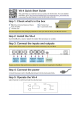
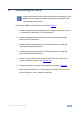
4 Connecting the VA-4 i Always switch off the power to each device before connecting it to your VA-4. After connecting your VA-4, connect its power and then switch on the power to each device. To connect the VA-4 as illustrated in the example in Figure 3: 1. Connect a balanced stereo audio source (for example, a set top box: source 1) to the left and right channel 1 IN XLR connectors. 2. Connect a balanced stereo audio source (Source 2) to the left and right channel 2 IN XLR connectors. 3.
Figure 3: Connecting the VA-4 Dual Channel Balanced Stereo Audio Amplifier 4.1 Connecting to the VA-4 via RS-232 You can connect to the unit via a crossed RS-232 connection, using for example, a PC. A crossed cable or null-modem is required as shown in method A and B respectively. If a shielded cable is used, connect the shield to pin 5.
5 4 3 2 9 8 7 6 9 8 7 6 1 5 4 3 2 PC 1 Figure 4: Crossed Cable RS-232 Connection Hardware flow control is not required for this unit. In the rare case where a controller requires hardware flow control, short pin 1 to 7 and 8, and pin 4 to 6 on the controller side. Method B (Figure 5)—Connect the RS-232 9-pin D-sub port on the unit via a straight (flat) cable to the null-modem adapter, and connect the null-modem adapter to the RS-232 9-pin D-sub port on the PC.
5 Technical Specifications INPUTS: 2 balanced stereo, up to 16dBm/33kΩ on female XLR connectors OUTPUTS: 2 balanced stereo, up to 21dBm/50Ω on male XLR connectors BANDWIDTH (-3dB): >100 kHz S/N RATIO: 80dB@6dB Gain (unweighted) CROSSTALK (all hostile): 74dB@1kHz; -68dB@20kHz CONTROLS: Level Control and Channel Selection, Impedance selection COUPLING: AC at output AUDIO THD + NOISE: 0.02%@1kHz AUDIO 2nd HARMONIC: 0.
6 Protocol 2000 The VA-4 is compatible with Kramer’s Protocol 2000 (version 0.51). This RS-232 / RS-485 communication protocol uses four bytes of information as defined below. For RS-232, a null-modem connection between the machine and controller is used. The default data rate is 9600 baud, with no parity, 8 data bits and 1 stop bit. The first table below lists the VA-4 Hex codes for gain control (attenuation), and the second table below lists the VA-4 Hex codes for gain control (amplification).
VA-4 Hex Codes for Gain Control (Attenuation) Gain (dB) -40.7 LED -166 Hex Codes 16 81 80 81 Gain (dB) -27.0 LED -110 Hex Codes 16 81 b8 81 Gain (dB) -13.2 -40.4 -165 16 81 81 81 -26.7 -109 16 81 b9 81 -13.0 -53 16 81 f1 81 -40.2 -164 16 81 82 81 -26.5 -108 16 81 ba 81 -12.7 -52 16 81 f2 81 -39.9 -163 16 81 83 81 -26.2 -107 16 81 bb 81 -12.5 -51 16 81 f3 81 -39.7 -162 16 81 84 81 -26.0 -106 16 81 bc 81 -12.3 -50 16 81 f4 81 -39.4 -161 16 81 85 81 -25.
VA-4 Hex Codes for Gain Control (Amplification) Gain (dB) 0 LED 0 Hex Codes 3f 80 81 81 16 81 a6 81 Gain (dB) +11.0 LED 45 +0.2 1 3f 80 81 81 16 81 a7 81 +11.3 46 Hex Codes 3f 80 81 81 16 81 d3 81 3f 80 81 81 16 81 d4 81 +0.5 2 3f 80 81 81 16 81 a8 81 +11.5 47 3f 80 81 81 16 81 d5 81 +0.7 3 3f 80 81 81 16 81 a9 81 +11.8 48 3f 80 81 81 16 81 d6 81 +1.0 4 3f 80 81 81 16 81 aa 81 +12.0 49 3f 80 81 81 16 81 d7 81 3f 80 81 81 16 81 d8 81 +1.2 5 3f 80 81 81 16 81 ab 81 +12.
14 VA-4 - Protocol 2000
For the latest information on our products and a list of Kramer distributors, visit our Web site where updates to this user manual may be found. We welcome your questions, comments, and feedback. Web site: www.kramerelectronics.com E-mail: info@kramerel.