
Instruction Manual


Communication Protocol
11
INSTRUCTION 32 – READ FRONT-PANEL SWITCH DATA
When sending to machine:- DATA = front-panel switch number; EXTENDED DATA - set as 0.
When replying:- DATA = front-panel switch number; EXTENDED DATA = front-panel switch value + 128.
The PC sends this instruction to the machine. The machine replies by sending back a value which relates to that switch.
INSTRUCTION 33 – WRITE FRONT-PANEL SWITCH DATA
DATA = front-panel switch number; EXTENDED DATA = front-panel switch value.
- The PC sends a value directly to the machine. If valid, the machine implements this new value, and replies by sending the
same data back to the PC. Note that the addressed front-panel switch does not need to be pressed in order to change its value
via RS-232.
- If the “+” or “-” button is pressed on the machine, resulting in a change in a switch value, then this switch number and value
is sent to the PC.
INSTRUCTION 61 – IDENTIFY MACHINE
For sending, DATA = 3 to request software version number. EXTENDED DATA - set to 0.
The PC sends this instruction to the machine. The machine replies as follows:
- If the software version is requested, the machine replies with DATA as the version number before the decimal
point, and EXTENDED DATA is the value following the decimal point. For example, for version 3.4, the machine replies
with DATA = 03 (hex), and EXTENDED DATA = 04 (hex).
FRONT-PANEL SWITCH DATA
INPUT SWITCH
The value of the switch data for the INPUT switch is defined as:
0 = CV
1 = YC
2 = YUV
3 = RGB/S
4 = SDI (FC-4001 only)
GENLOCK SWITCH
The value of the switch data for the GENLOCK switch is defined as:
1 = Machine is in Genlock mode.
0 = Machine is not in Genlock mode.
GENLOCK_STAT SWITCH (inner switch, not on front panel)
The value of the switch data for the GENLOCK_STAT switch is defined, when GENLOCK is ON, as:
1 = Machine is Genlocked to input.
0 = Machine is not Genlocked to input.
PANEL_LOCK SWITCH
The value of the switch data for the PANEL_LOCK switch is defined as:
1 = Machine's front panel is locked.
0 = Machine's front panel isn't locked.
FREEZE_SWITCH
The value of the switch data for the FREEZE switch is defined as:
1 = Freeze is ON.
0 = Freeze is OFF.
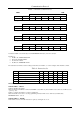
Table 9 contains the front-panel switch numbers, as defined for this protocol, and indicates the information which may be read
(status, data) on each switch:
Table 9: Front-Panel Switch Numbers
SWITCH D4 D3 D2 D1 D0 STATUS DATA
Select Input Format
0 0 0 0 0 NO YES
Genlock 1 0 1 1 0 YES NO
Panel lock 1 0 1 1 1 YES NO
Freeze 1 1 0 1 0 YES NO
Genlock Stat 1 1 1 0 0 YES NO