
Instruction Manual


KRAMER: SIMPLE CREATIVE TECHNOLOGY
Communication Protocol
10
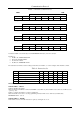
Table 7: Structure of the Protocol
MSB LSB
INSTRUCTION
0 TO PC I5 I4 I3 I2 I1 I0
7 6 5 4 3 2 1 0
1st byte
DATA
1 D6 D5 D4 D3 D2 D1 D0
7 6 5 4 3 2 1 0
2nd byte
EXTENDED DATA
1 E6 E5 E4 E3 E2 E1 E0
7 6 5 4 3 2 1 0
3rd byte
MSB’s ADDR
1 E7 D7 1 1 0 0 0
7 6 5 4 3 2 1 0
4th byte
Note that the MSB’s of the DATA (D7) and the EXTENDED DATA (E7) are in the fourth byte.
Terminology:
TO PC is the “DESTINATION BIT”
I4..I0 is the “INSTRUCTION”
D7..D0 is the “DATA”
E7..E0 is the “EXTENDED DATA”
The destination bit, TO PC, is 0 when sending from the PC to the machine, or 1 when sending from the machine to the PC.
Table 8: Instruction Set
# INSTRUCTION I5 I4 I3 I2 I1 I0
0 Reset 0 0 0 0 0 0
16 Error 0 1 0 0 0 0
32 Read front-panel switch data 1 0 0 0 0 0
33 Write front-panel switch data 1 0 0 0 0 1
61 Identify machine 1 1 1 1 0 1
DESCRIPTION OF INSTRUCTIONS
INSTRUCTION 0 – RESET
DATA=0: initialize the machine.
When the machine is initialized, it will send the RESET code (DATA = 0). If the machine receives this code, it will reset to its
“power-up” state.
DATA=1: configure the machine to its factory default state.
When the machine receives this code, all programmable parameters will be reset to their factory-default values.
EXTENDED DATA - set as 0.
INSTRUCTION 16 – ERROR
If the machine receives an invalid instruction, it replies by sending this error code.