
User's Manual

BSR100D™ Wireless Radio Modem Page 11 User Manual
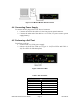
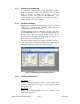
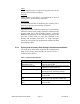
Figure 7: PC/ Modem Module DTE Connection
4.4 Connecting Power Supply
To connect the DC plug to the J3 DC Power Connector:
1. Connect one end of the cable to J3, the four-pin rear panel connector.
2. Connect the other end of the cable to a 12.5 VDC, 5A power source (power
supply/battery)
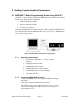
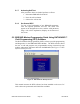
4.5 Performing a Self Test
To perform a self test:
1. Switch on the 12.5 VDC power supply
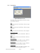
2. Observe the Self-Test LEDs (see Figure 8: Self-Test LEDs and Table 6:
Self-Test LEDs for full description)
Figure 8: Self-Test LEDs
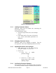
Table 6: Self-Test LEDs
LED Indicator Status
LED PTT
ON (red) Tx mode
OFF Rx mode
2 Flashes Overload (optional)
3 Flashes Predriver/Driver
1 Flash Time out timer
4 Flashes PLL
4 Flashes Synthesizer