2’x20’ Alexander Hardtop Gazebo With Double Roof Assembly Manual Kozyard LLC Products www.kozyard.com © Copyright 2016 - 2023 Kozyard LLC. | All Rights Reserved.
Warnings and Cautions • Please read and follow this assembly and operation guide to reduce the risk of personal injury and damage to your gazebo. • Do not discard any of the packaging until you have checked that you have all the parts in place. The maximum weight capacity of this gazebo roof is 2500 pounds. • Sidewalls and nettings should be off or in the opened position and tied to poles when winds are over 30 MPH to avoid damage. • Some parts may have sharp edges or corners.
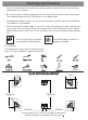
Attention: Prior to assembly, verify that all parts and pieces are included to ensure an efficient installation process.
P12 x2 P2 x2 Q9 x2 Q10 x2 W11 x2 W12 x2 W13 x2 W14 x2 Q19 x2 Q20 x2 R x8 R1 x2 S x160 T2 x2 T9 x2 T10 x2 U1 x4 U9 x4 U10 x4 U4 x8 U3 x4 V11 x2 V23 x2 V24 x2 V12 x2 V x8 V25 x2 V26 x2 12’x20’ assembly manual W15 x2 ITEM P2 P12 Q9 Q10 Q19 Q20 R R1 S T2 T9 T10 U1 U3 U4 U9 U10 V11 V12 V23 V24 V V25 V26 W11 W12 W13 W14 W15 W16 W17 W18 W16 x2 W17 x2 W18 x2 DESCRIPTION QTY 2 2 2 2 2 2 8 2 160 2 2 2 4 4 8 4 4 2 2 2 2 8 2 2 2 2 2 2 2 2 2 2 Finishing Bar Net Frame Finishing Bar Finishing
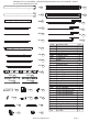
6# x8+1 7# x48+2 8# x6+1 X21 x2 X22 x2 X23 x2 X24 x2 X25 x2 X26 x2 9# x28+2 10# x4+1 11# x12+1 X27 x2 X28 x2 X29 x2 Allen key X30 x2 X31 x2 X32 x2 Wrench Screw Driver Y7 x4 ITEM DESCRIPTION X21 X22 X23 X24 X25 X26 X27 X28 X29 X30 X31 X32 Y7/Y9 Z Z1 Z2 Z3 Z4 1# 2# 3# 4# 5# 6# 7# 8# 9# 10# 11# Roof Panel Roof Panel Roof Panel Roof Panel Roof Panel Roof Panel Roof Panel Roof Panel Roof Panel Roof Panel Roof Panel Roof Panel Y9 x2 Z x72+2 Z1 x6 Z2 x6 Z3 x2 Z4 x2 4# x76+2 1# x301+5 2# x28+2
Step 1:Set up Poles Parts Required: Set up Poles (Part A, A1) with Stand Plates (Part L , L1) using screws 1# as shown in diagram. X4 A 1# 1# 1# A A x4 L L x4 L 1# x12 Reference for anchoring gazebo: • A1 1# 1# A1 1# • If the ground is concrete and its depth is over 3 inches, you can purchase 3/8" diameter x 3" length sleeve anchors. Only anchor after finishing all the assembly.
Parts Required: C6 x4 F x6 B6 x4 1# E2 x2 x24 Step 2: Connect the Beams 1. Connect (Part C6,B6) into one beam using Union bar (Part F) with screws 1# as shown in the diagram. Short Beam Overall: C6 X2 B6 F B6 B6 C6 X2 C6 1# F 1# 1# 1# 2. Connect (Part C6, E2, B6) into one beam using Union Bar (Part F) with screws 1# as shown in the diagram.
Parts Required: C61 x2 B61 x2 C62 x2 B62 x2 C21 x2 E21L x2 E21R x2 B21 x2 1# x108 C62 x2 B62 x2 Step 3: Connect Joint Bars with Beams C61 12 ft overall: C6 C62 20 ft overall: C21 C6 C62 B61 B62 E21L B6 E21R B21 E2 B6 B6 B62 Tip: Do not tighten all screws on Jointer Bar (Part B61,C61,B21,E21R,E21L,C21), until the screws of the roof panels be aligned in place. C6 1# 1# B62 X2 1# 1# X2 C62 B61,B21 C61,C21 1. Connect Joint Bars (Part B61,B21) and 2.
Parts Required: 2# x28 1# x16 3# E22R x2 E22L x2 x16 Step 4: Set up Poles and Beams Use screws 3# first, then screw 2# to connect Poles and Beams together as shown in diagram. X8 3# 3# ① A B6 X2 Tip: Place parts on carpet or rug to avoid scratches during assembly. C6 A ② X8 2# 2# C6 B6 ③ B6 ② E2 C6 2# E2 ① B6 C6 X2 2# X2 2# A1 ③ 2. Connect Joint Bars (Part E22L,E22R) to Beam (Part E2) using screws 1# as shown in diagram.
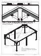
Parts Required: J1 x4 1# J2 x4 J1 x32 J2 1# 1# 1# Step 5: Connect Solidifying Bars with Beams and Poles X4 Affix the frame with Corner Solidifying Bars (Part J1,J2) using screws 1# as shown in the diagram. J1 J2 J1 l1 Diagona na l2 J2 Dia go J2 J1 J2 J1 Diagonal 1 = Diagonal 2 Tip: Measure (DIAGONALLY) from posts to posts to assure alignment so all materials fit as planned.
Parts Required: G x4 9# H x6 Step 6: Cover the connections x28 9# 1. Finish Connecting Beams using Corner Covers (Part G) and screws 9# as shown in the diagram. 9# G 9# X4 ① ① ② ② ① ② ① ② ② ② ① ② X6 2. Affix Middle Beams using Joint Cover (Part H) and screws 9# as shown in diagram.
Parts Required: H2 x1 Step 7: Seal the seams 1. After finishing Step 6, apply silicone rubber to the seams to ensure they're watertight. 2. If the screws are correctly attached through Spacer part S on the roof panels, sealing the cap screws with silicone rubber isn't necessary.
Parts Required: 4# H1 x6 x76 8# x6 Step 8: Install Hooks ③ After finishing Hooks (Part 4#) into the tracks, then put Joint Cover (Part H1) to lock them. ① ② ② ① ③ 4# X6 4# 4# Note the amount of hooks for each slot as noted below: ① Put H1 8# X2 7 hooks to each slot of Sidewall Track (Part C62 , Part B62) for 12 ft side 4# x7 C6 C62 H1 B6 x7 B62 ② Put 7 hooks to each slot of Sidewall Track Part C62 and 5 hooks to each slot Sidewall track Part E22L for 20 ft side.
Parts Required: N1 x2 M4 x4 N2 x2 1# x36 N3 x4 K10 x1 Step 9: Set up roof frame N3 N2 N3 1# 1# hole N1 1# 1# 1# 1# ① K10 N1 1# Upward View N2 N3 N3 hole M4 M4 1# M4 hole 1# hole M4 N3 M4 M4 N2 1# 1# N2 N3 1# 1# 1# N1 1# N3 M4 X2 A1 A ① X4 ② X2 ③ N2 1. Connect the inside roof connector (Part K10) with the conner roof bar(Part M4) and roof bar(Part N1,N2,N3) using screws 1# as shown in diagram.
Parts Required: Q9 x2 P2 x2 M4 ① N3 Q9 ② N2 Q10 1# R x4 Q10 x2 x6 N3 ① M4 P2 N1 N1 P2 ① Upward View ② Q 10 M4 ① Q9 N2 N3 M4 N3 ① ② 1# R Q10 P2 N2 Q10 X4 X2 Step 10: Set up Roof Bar Q9 2. Affix the Finishing Bar (Part Q9, Q10) to the roof bars (Part N2, N3) using screw 1# as shown in the diagram. 1. Attach the finishing bar (Part P2, Q9, Q10) with the finishing end (Part R) using screw 1# to the corner roof bar (Part M3) as shown in the diagram.
Parts Required: 1# K20 x1 x5 Upward View K10 K20 1# 1# 1# Step 11: Connect Outside Roof Connctor Connect the Outside Roof Connector (Part K20) to the Inside Roof Connector (Part K10) using screw 1#, as shown in the diagram.
Parts Required: Z x12 Z1 x4 V11 x2 V12 x2 V24 x2 V23 x2 V25 x2 V x8 Z2 x4 V26 x2 Z3 x2 Z4 x2 H3 x1 Step 12: Snap Bracket Snap Bracket (Part Z, Z1, Z2, Z3, Z4) to the roof panel edges as shown in the diagram. (with snaps facing upwards) X2 Z1 Z2 Z Z Z Z2 Z1 V12 V11 Z Z Z4 V23 V V24 V Z Z Z3 V V V25 V26 Tips: 1. Wearing protective gloves is recommended. 2.
Parts Required: 1# T9 x2 T2 x2 R x4 T10 x2 x12 R1 x2 Upward View V26 V25 R T2 1# V T10 T9 V V V24 V23 V R V12 V11 T2 V11 V12 R V23 V24 V R 1# T9 V 1# R1 V V V25 V26 T10 1# 1# X2 Step 13: Assemble Roof Panel 1. Push the Roof Panels (Part V11, V12, V23, V24, V, V, V25, V26) up to the upper roof as shown in the diagram. 2. Attach Finishing Bars (Part T2, T9, T10) to the upper roof with Finish End (Part R) using screws #1, as shown in the diagram.
Parts Required: U1 x4 U3 x4 U9 x4 1# U4 x8 x36 U10 x4 Step 14: Connect Solidifying Bars 1. Connect the U10 Bars at the ends where the holes are 5.1” apart to one another using screw 1# as shown in diagram. 1# U4 1# U10 5.1” 3.3” 5.1” U9 ② U10 3.
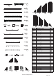
Parts Required: x32 W11 x2 W12 x2 W13 x2 W14 x2 W15 x2 W16 x2 H3 x1 W17 x2 W18 x2 Step 15: Snap Bracket Snap Brackets (Part Z) to roof panel edges as shown in the diagram. (with snaps facing upwards) Z X2 Z Z Z Z Z Z Z Z W11 W12 Tips: W13 W14 1. Wearing protective gloves is recommended. 2.
Parts Required: Z x28 Z1 x2 X21 x2 X22 x2 X23 x2 X24 x2 X25 x2 X26 x2 X27 x2 X28 x2 X29 x2 X30 x2 X31 x2 H3 x1 Z2 x2 X32 x2 Step 16: Snap Bracket Snap Brackets (Part Z, Z1, Z2) to roof panel edges as shown in the diagram. (with snaps facing upwards) X2 Z Z Z Z Z Z Z Z Z2 X21 Tips: X22 X24 X23 X25 X26 1. Wearing protective gloves is recommended. 2.
Overall roof assembly: Please place the panels on the frame and assemble them from the centerline (Part N1, N2) to the left and right. X21 N2 X24 X26 X32 X31 X30 X28 X29 W18 W17 W16 W15 W14 W13 W12 W11 N1 X22 X23 X25 X27 W11 W12 W17 W18 X26 X23 X25 2 X22 X24 X28 X30 N W13 W14 W15 W16 X27 X29 X32 X31 X21 N1 Connect roof as below: Tip: Wearing protective gloves is recommended.
Parts Required: S x160 L 28mm 5# 6# 7# x100 x8 x48 L 45mm L 50mm 10# L 25mm x4 Step 17: Affix roof panels using screws and Spacers (Part S) as shown in the diagram. 10# 6# Align all roof panels and screws LOOSELY (DO NOT TIGHTEN ANY SCREWS) until all the roof panels are aligned accordingly. THEN, TIGHTEN all screws to secure the roof panels in place. S ① S ② ② X4 6# X8 ① ① ② ② ③ ② ④ ④ ③ ④ ④ ④ X100 X48 ③ 5# 7# S 2+ Tip: At least two people for this step.
Parts Required: P12 x2 Q19 x2 11# 1# x6 Q20 x2 x12 Step 18: Assemble Net Frames Attach net frame (Part P12, Q19, Q20) to finishing bar(Part P2, Q9, Q10) using screws (1#, 11#) as shown in the diagram.
Parts Required: Y7 x2 Y9 x2 Step 19: Assemble Net and Sidewall Install the Mosquito Net on the inner rails and the Solid Sidewalls on the outer rails as shown in the diagram.
Parts Required: Step 20: When closing the Mosquito Net, refer to the steps below to align it with the poles, as shown in the diagram. ① (Not included) Y7,Y9 ③ ④ ⑤ ② SY (Not included) Y7,Y9 (Not included) Y7,Y9 (Not included) Y7,Y9 Care and Warranty • Cleanse the frame components and fabric using a mild soap solution, then rinse thoroughly. Refrain from using bleach, acid, or any other solvents on the fabric or frame components.
Thank you for your purchase of KOZYARD’s gazebo. As expert manufacturer of hardtop gazebos, Kozyard remains committed to supporting you with parts and replacements, even beyond your warranty period. Don't hesitate to contact us directly if you are missing parts or need a replacement. 66 Kozyard LLC © Copyright 2016 - 2023 Kozyard LLC. | All Rights Reserved.