
Use and Care Manual

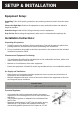


Equipment Setup:
Unpacking: Take off all packing materials, tape, and any protective plastic from the equip-
ment.
Choose the Right Spot: Position the equipment at your preferred location and adjust its
height as needed.
Attach the Legs: Install all four (4) legs securely onto the equipment.
Prep for Use: Before using the equipment, make sure it is cleaned and completely dry.
Installation Instructions:
Unpacking & Inspection:
1. Carefully remove the appliance from its packaging. Take off all protective plastic film,
packing materials, and accessories before proceeding with installation.
2. Prior to installation, thoroughly review the instructions in this manual and the included
Installation Instruction Sheet.
Clearance and Equipment Positioning:
• This equipment should only be installed next to non-combustible surfaces, with a mini-
mum 6-inch clearance from all sides.
• Maintain a 6-inch distance from other equipment.
• Ensure the equipment is fitted with 4-inch legs and placed on a non-combustible surface.
Air Supply and Ventilation:
• Keep the area in front and around the equipment clear to prevent any obstruction of
combustion and ventilation airflow.
• Maintain adequate clearance in front of and on the sides of the equipment to allow for
servicing and proper ventilation.
Product parameters table
times in front of and at the sides of the
.
ave a pressure regulator on the incoming
The regulator provided for this equipment
outlet, factory adjusted for 4” WC Natural
fied personnel to be used for Propane at
Pressure Regulator:
• All commercial cooking equipment requires a pressure
regulator on the incoming service line for safe and efficient
operation.
• The provided regulator is adaptable for both Natural Gas
and LP Gas.
• Regulator specifications: ¾” NPT inlet and outlet, factory
adjusted for 4” WC Natural Gas standard, and can be
converted by qualified personnel for Propane at 10” WC.
Gas Conversion:
• Conversion from Natural Gas to Liquid Propane (LP) or vice versa can only be performed by the
factory or its authorized service agent.
• Ensure the correct orifice sizes of the spuds are provided.
• Natural Gas Orifice: #37
• Liquid Propane Gas Orifice: #51
• Orifice size is indicated on the spud.
Lighting the Pilot:
1. Before attempting to light the pilots, turn off the main gas valve to the equipment and wait for 5
minutes to allow the gas to clear.
2. Turn off all gas control knobs.
3. Turn on the control valve and ignite all pilots.
4. The pilot burner should be ignited at the end of the tube. Hold an ignition source through the
pilot light hole in the front panel at the pilot tube. Remove the ignition source when the flame
ignites.
5. To shut down the equipment, turn off the main gas valve.
It's normal for some smoke to appear during initial use as the rust preventative coating burns off.
Allow the equipment to "burn in" for at least 15 minutes before the first use.
Pilot Flame Regulation:
• The pilot flame is factory adjusted. If adjustment is needed, make the pilot flame as small as
possible but high enough to immediately light the burner when the burner valve is turned to the
highest setting. Access to the pilot flame adjustment screw is obtained by removing the front
panel.
Burner Adjustment:
• Remove the front panel for access. Turn the burner valve knob to the highest setting.
• Gradually decrease the mixing ring aperture to achieve a soft blue flame with luminous tips.
• Slowly increase the opening until the yellow tips disappear, and a hard blue flame is obtained.
Follow these instructions for the safe and efficient installation of your equipment.
Model No.
Dimensions
(W x D x H)
Griddle Plate Size
(W x D x Thickness)
Power
(BTU/hr)
Number of
Burners
KM-GG1-18M
17.91" x 24.41"
x 16.14"
17.83" x 19.09" x 0.63" 30,000 1
KM-GG2-24M
23.62" x 24.41"
x 16.14"
23.54" x 19.09" x 0.63" 60,000 2
KM-GG3-36M
35.43" x 24.41"
x 16.14"
35.35" x 19.09" x 0.63" 90,000 3
KM-GG4-48M
47.24" x 24.41"
x 16.14"
47.17" x 19.09" x 0.75" 120,000 4