DUAL FUEL RANGE Installation Manual Professional Style Range MODEL: KM-FR36DF-SS Installation Manual IMPORTANT: Read and save these instructions. NOTICE: Installer: Leave this guide with the homeowner. Homeowner: Keep this guide for future reference.
TABLE OF CONTENTS RANGE SAFETY ............................................................................................... 3 Anti-tip Device ........................................................................................................... 4 INSTALLATION REQUIREMENTS .................................................................... 6 Tools and Parts .......................................................................................................... 6 Location Requirements .............
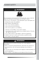
RANGE SAFETY WARNING Fire Hazard If the information in this manual is not followed exactly, a fire or explosion may result causing property damage, personal injury or death. - Do not store or use gasoline or other flammable vapors and liquids in the vicinity of this or any other appliance. - WHAT TO DO IF YOU SMELL GAS • Do not try to light any appliance. • Do not touch any electrical switch. • Do not use any phone in your building. • Clear the room, building, or area of all occupants.
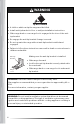
WARNING Tip Over Hazard • A child or adult can tip the range and be killed. • Install anti-tip bracket to floor or wall per installation instructions. • Slide range back so rear range foot is engaged in the slow of the antitop bracket. • Re-engage the anti-tip bracket if range is moved. • Do not operate the range without anti-tip bracket installed and engaged. • Failure to follow these instructions can result in death or serious burns to children and adults.
Your safety and the safety of others are very important. We have provided many important safety messages in this manual and on your appliance. Always read and obey all safety messages. This is the safety alert symbol. This symbol alerts you to potential hazards that can kill or hurt you and others. All safety messages will follow the safety alert symbol and either the word "DANGER," "WARNING" or "CAUTION.
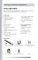
INSTALLATION REQUIREMENTS TOOLS AND PARTS Gather the required tools and parts before starting installation. Read and follow the instructions provided with any tools listed here. Tools Needed • Tape measure • 3/16" (4.8 mm) carbide-tipped masonry drill bit (for concrete/ceramic floors) • Flat-blade screwdriver • Phillips screwdriver • Noncorrosive leak-detection solution • Level • Drill • Wrench or pliers • Pipe wrench For Propane/Natural Gas Conversions • 15/16" (2.4 cm) combination wrench • 1/2" (1.
Parts Needed Gas supply line kit (supply line and 2 adapters) • LP conversion kits 7
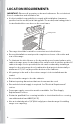
LOCATION REQUIREMENTS IMPORTANT: Observe all governing codes and ordinances. Do not obstruct flow of combustion and ventilation air. • It is the installer's responsibility to comply with installation clearances specified on the model/serial rating plate. The model/serial rating plate is located behind the oven door on the oven frame. Rating Plate • The range should be located for convenient use in the kitchen. • Recessed installations must provide complete enclosure of the sides and rear of the range.
Mobile Home - Additional Installation Requirements • The installation of this range must conform to the Manufactured Home Construction and Safety Standard, Title 24 CFR, Part 3280 (formerly the Federal Standard for Mobile Home Construction and Safety, Title 24, HUD Part 280). When such standard is not applicable, use the Standard for Manufactured Home Installations, ANSI A225.1/NFPA 501A or with local codes.
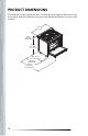
PRODUCT DIMENSIONS This manual covers several models. Your model may appear different from the models depicted. Dimensions given are maximum dimensions across all models. 35.4 in (900 mm) 1.77 in (45 mm) Vent height 35.4 in (900 mm) To cooktop 25.0 in (635 mm) 27.0 in (686 mm) With handle 42.
CLEARANCES IMPORTANT: Some cabinet and building materials are not designed to withstand the heat produced by the oven for baking and self-cleaning. Check with your builder or cabinet supplier to make sure that the materials used will not discolor, delaminate or sustain other damage. GIVEN DIMENSIONS ARE MINIMUM CLEARANCES. 35.6 in (90.5 cm) 18 in (45.7 cm) 36 in (91.4 cm) 6 in (15.2 cm) to left wall 30 in (76.2 cm) 6 in (15.2 cm) to right wall 13 in (33 cm) Maximum Overhead Cabinet Depth 25 in (63.
VENTING REQUIREMENTS IMPORTANT: This range must be exhausted outdoors unless you are using ductless venting. Observe all governing codes and ordinances. Do not obstruct flow of combustion and ventilation air. • Do not terminate the vent system in an attic or other enclosed area. • Use an approved vent cap for proper performance. If an alternate wall or roof cap is used, be certain the cap size is not reduced and that it has a backdraft damper.
ELECTRICAL REQUIREMENTS WARNING Electrical Shock Hazard The electrical power to the oven branch circuit must be shut off while line connections are being made. Do not use an extension cord with this appliance. Electrical ground is required on this appliance. The free end of the green wire (the ground wire) must be connected to a suitable ground. This wire must remain grounded to the oven.
ELECTRICAL SPECIFICATIONS COMPONENT WATTAGE Upper Inner Heating Element 3158W Upper Outer Heating Element 2395W Rear Heating Elements 2 x 1250W Lower Heating Element 1960W Oven Lights 2 x 25W Convection Fan Motors 2 x 16W Cooling Fan Motor 23W ELECTRICAL REQUIREMENTS - U.S.A. ONLY If codes permit and a separate ground wire is used, it is recommended that a qualified electrical installer determine that the ground path is adequate and wire gauge is in accordance with local codes.
• Allow 3 ft - 6 ft (0.9 m - 1.8 m) of slack in the line so that the range can be moved if servicing is ever necessary. • A UL listed conduit connector must be provided at each end of the power supply cable (at the range and at the junction box). • The electrical supply should be a 3-wire or 4-wire, two-phase AC. Install a suitable conduit box (not furnished). An appropriately sized, U-listed conduit connector must be used to correctly attach the conduit to the junction box.
Be sure that the electrical connection and wire size are adequate and in conformance with CSA Standard C22.1, Canadian Electrical Code, Part 1 latest edition, and all local codes and ordinances. A copy of the above code standards can be obtained from: Canadian Standards Association 178 Rexdale Blvd. Toronto, ON M9W 1R3 CANADA Electrical Connection Check local codes and consult gas supplier. Check existing electrical supply and gas supply.
GAS SUPPLY REQUIREMENTS WARNING Explosion Hazard Use a new CSA International approved gas supply line. Install a shut-off valve. Securely tighten all gas connections. If connected to LP, have a qualified person make sure gas pressure does not exceed 14" (36 cm) water column. Examples of a qualified person include: • licensed heating personnel, • authorized gas company personnel, and • authorized service personnel. Failure to do so can result in death, explosion or fire.
LP Gas Conversion: Conversion must be performed by a qualified service technician. The qualified agency performing this work assumes the gas conversion responsibility. No attempt shall be made to convert the appliance from the gas specified on the model/serial rating plate for use with a different gas without consulting the serving gas supplier. See "GAS CONVERSION" section. GAS SUPPLY LINE Provide a gas supply line of 3/4" (1.9 cm) rigid pipe to the range location.
Gas shutoff valve: A manual gas line shut-off valve must be installed in an easily accessible location. Do not block access to shut-off valve. The valve is for turning on or shutting off gas to the range. a b c a Gas Supply Line b Shutoff Valve "Open" Position c To Range GAS PRESSURE REGULATOR The gas pressure regulator supplied with this range must be used.
INSTALLATION INSTRUCTIONS IMPORTANT: This appliance shall be installed only by authorized persons and in accordance with the manufacturer's installation instructions, local gas fitting regulations, municipal building codes, electrical wiring regulations, local water supply regulations. UNPACK RANGE WARNING Excessive Weight Hazard Use two or more people to move and install range. Failure to do so can result in back or other injury. 1. Remove shipping materials, tape and film from the range.
INSTALL ANTI-TIP DEVICE WARNING Tip Over Hazard • A child or adult can tip the range and be killed. • Install anti-tip bracket to floor or wall per installation instructions. • Slide range back so rear range foot is engaged in the slow of the antitop bracket. • Re-engage the anti-tip bracket if range is moved. • Do not operate the range without anti-tip bracket installed and engaged. • Failure to follow these instructions can result in death or serious burns to children and adults.
2. Place the bracket so that the back of the bracket is against the rear wall and the side edge of the bracket is 3/8" to 1/2" from the adjacent cabinet. NOTE: If there is no adjacent cabinet, place the bracket so that the edge of the bracket is 3/8" to 1/2" in from the range side panel. If the countertop overhangs the cabinet, offset the bracket from the cabinet by the depth of the overhang plus an additional 3/8" to 1/2". 3.
5. Install the anti-tip bracket. Wood • Using the two screws (provided) fasten the anti-tip bracket to the floor or wall. NOTE: The screw must enter wood or metal. Concrete • Insert the sleeve anchor into the drilled holes and then insert the lag bolts through the anti-tip bracket and into the floor or wall. The bolts must be properly tightened as recommended for the hardware. INSTALL ANTI-TIP CHAIN (F965 ONLY) 1. Remove the anti-tip wall anchor hooks and screws from the parts bag. 2.
INSTALL BACKSPLASH • Install the backsplash to rear of range with the screws provided. ELECTRICAL CONNECTION INSTALL USING A POWER SUPPLY CORD WARNING Electrical Shock Hazard Disconnect power before servicing. Use a new 40 amp power supply cord. Plug into a grounded outlet. Failure to do so can result in death, fire, or electrical shock.
Power supply cord strain relief 1. Disconnect power. 2. Remove the terminal block cover screws located on the back of the range. Pull the cover down and toward you to remove cover. Terminal block access (F965NF only) 3. Remove the knockout for the 40-amp supply cord, and assemble a UL listed strain relief in the opening. a UL Listed Strain Relief b Bottom Panel c Power Cord 4.
3-Wire Connection: Power Supply Cord Use this method only if local codes permit connecting chassis ground conductor to neutral wire of power supply cord. a e b c f d a b c d Terminal Block Strain Relief e f Jumper Wire Ground Screw Strain Relief Nut Power Supply Cord 1. Use 3/8" (1.0 cm) nut driver to connect the ground (green) wire from the power supply cord to the center terminal block post with one of the 10-32 hex nuts. 2.
4-Wire Connection: Power Supply Cord Use this method for new branch-circuit installations (1996 NEC), mobile homes, recreational vehicles, or in an area where local codes prohibit grounding through the neutral. a e b f c d a b c d Terminal Block Strain Relief e f Jumper Wire Ground Screw Strain Relief Nut Power Supply Cord 1. Use a Phillips screwdriver to remove the ground screw and disconnect the green ground wire. 2. Use 3/8" (1.
6. Firmly tighten hex nuts. NOTE: For power supply cord replacement, use only a power cord rated at 250V minimum, 40 or 50 A that is marked for use with nominal 1 3/8" (3.5 cm) diameter connection opening, with ring terminals and marked for use with ranges. 7. Verify the strain relief is positioned over the insulation layer of power supply cord but not its wires, and tighten the strain relief screws. IMPORTANT: Verify the tightness of the hex nuts. 8. Replace the terminal block cover.
Your local codes and ordinances, of course, take precedence over these instructions. Complete electrical connections according to local codes and ordinances. Direct wire strain relief 1. Disconnect power. 2. Remove the terminal block cover screws located on the back of the range. Pull the cover down and toward you to remove cover. Terminal block access (F965NF only) 3. Remove the knockout for the 40-amp supply cord, and assemble a UL listed conduit connector in the opening.
4. Feed the flexible conduit through the conduit connector, and tighten strain relief screw against the flexible conduit. 5. Complete installation following instructions for your type of electrical connection: • 4-wire (recommended) • 3-Wire (if 4-wire is not available) 3-Wire Connection: Direct Wire Use this method only if local codes permit connecting ground conductor to neutral supply wire.
Grounded Neutral a h b c g d e f a b c d e f Junction Box g h Black Wires Red Wires White Wires Green Wire Cable from Oven UL Listed Conduit Connector Cable from Power Supply 4-Wire Connection: Direct Wire Use this method for new branch-circuit installations (1996 NEC), mobile homes, recreational vehicles, or in an area where local codes prohibit grounding through the neutral. 1. Disconnect ground from neutral at free end of conduit. 2.
Ungrounded Neutral a h g b c d f e a b c d e Junction Box f g h Black Wires Red Wires Green Wires Cable from Oven UL Listed Conduit Connector White Wires Cable from Power Supply GAS CONNECTION WARNING Explosion Hazard Use a new CSA International approved gas supply line. Install a shut-off valve. Securely tighten all gas connections. If connected to LP, have a qualified person make sure gas pressure does not exceed 14" (36 cm) water column.
This appliance shall be installed only by authorized persons and in accordance with the manufacturer's installation instructions, local gas fitting regulations, municipal building codes, electrical wiring regulations, local water supply regulations. This range is factory-set for use with Natural gas. To use this range with Propane gas, see the "GAS CONVERSION section before connecting this range to the gas supply.
1. Apply pipe-joint compound made for use with LP gas to all pipe thread connections. 2. Using a pipe wrench to tighten, connect the gas supply to the range. a b c d a b c d Gas Line from Range Washer (provided) Adapter (provided) Gas Pressure Regulator (provided) CONVERT TO LP GAS (OPTIONAL) This range is shipped from the factory set up to use natural gas. It can be converted to use LP gas by a qualified service technician. The LP conversion kit is sold separately.
COMPLETE CONNECTION WARNING Electrical Shock Hazard Disconnect power before servicing. Plug into a grounded 3-prong outlet. Do not use an adapter or an extension cord. Failure to do so can result in death, fire, or electrical shock 1. Open the manual shutoff valve in the gas supply line. The valve is open when the handle is parallel to the gas pipe. 2. Test all connections by brushing on an approved noncorrosive leakdetection solution. If bubbles appear, a leak is indicated. Correct any leak found. 3.
Note: Align notches in burner caps with pins in burner base. Burner caps should be level when properly positioned. If burner caps are not properly positioned, surface burners will not light. Cap Incorrectly Positioned Base Auxiliary Burner Semi Rapid Burner Rapid Burner Correctly Positioned Triple Ring Burner 4. Place burner grates over burners and caps. 5. Plug in range or reconnect power. ADJUST FLAME HEIGHT Check and adjust the height of top burner flames.
The flame can be adjusted using the adjustment screw in the center of the valve stem. The valve stem is located directly behind the control knob. 1. Light the burner and turn the knob to the lowest setting (MIN). 2. Pull and remove the control knob. 3. Insert a small, flat-blade screwdriver into the adjustment screw, and slowly turn the screw until the flame appearance is correct. • Open the valve more if the flames are too small or fluttered. • Close the valve more if the flames are too large.
LEVEL RANGE IMPORTANT: Do not operate the range if its rear foot is not completely engaged in the anti-tip bracket. Never completely remove the leveling legs or the range will not be secured to the anti-tip device properly. 1. Slide range into final location, making sure rear leveling leg slides into the anti- tip bracket. Leave a 1" (2.5 cm) gap between the back of the range and the back wall. 2. Check that the range is level by placing a level on the oven bottom.
2. Slowly attempt to tilt the range forward. • If you encounter immediate resistance, the range foot is engaged in the anti-tip bracket. Range installation is completed. • If the rear of the range lifts more than 1/2" (1.3 cm) off the floor without resistance, stop tilting the range and lower it gently back to the floor. The range foot is not engaged in the anti-tip bracket. Proceed to Steps 3 and 4.
GAS CONVERSION WARNING Explosion Hazard Use a new CSA International approved gas supply line. Install a shut-off valve. Securely tighten all gas connections. If connected to LP, have a qualified person make sure gas pressure does not exceed 14" (36 cm) water column. Examples of a qualified person include: • licensed heating personnel, • authorized gas company personnel, and • authorized service personnel. Failure to do so can result in death, explosion or fire.
LP/PROPANE GAS CONVERSION IMPORTANT: Gas conversions must be done by a qualified service technician in accordance with the manufacturer's instructions and all codes and requirements of the authority having jurisdiction. The qualified agency performing this work assumes the gas conversion responsibility. Convert Gas Pressure Regulator 1. Turn manual shutoff valve to the closed position. 2. Unplug range or disconnect power. 3. Locate the gas pressure regulator on the back of the range.
7. Screw and tighten the regulator cap back into the gas pressure regulator with the wrench. «¢ª¥¨ ¦ Convert Surface Burners 1. If installed, remove the burner grates. 2. Remove the burner grates, burner caps, and the burner base. 3. Remove the natural gas orifices with a 9/32" (7 mm) nut driver. ¨ 4. Replace the natural gas orifices with the correct LP gas orifices from the LP conversion kits. LP gas orifices are stamped with a size.
Orifice Chart for Surface Burners: F965 / F965NF LP Orifice NG Orifice Burner Rating Size (mm) Size (mm) Burner Placement Rapid Front Left 0.91 1.45 9,500 BTU Auxiliary Front Right 0.70 1.05 5,000 BTU Triple Ring Center 1.22 2.10 18,000 BTU Semi Rapid Rear Left 0.81 1.29 7,500 BTU Semi Rapid Rear Right 0.81 1.29 7,500 BTU A. Rapid (Large) B. Auxiliary (Small) D D C. Triple Ring (X-Large) C A D. Semi Rapid (Medium) B 5.
Complete Gas Conversion • Refer to "Gas Connection" section in the "Installation Instructions" section for proper connection of the range to the gas supply. • Refer to "Complete Connection" section to complete this procedure. • Refer to the "Adjust Flame Height" section for burner flame adjustments. IMPORTANT: You may have to adjust the low setting for each cooktop burner. Correct Disposal of this product: This marking indicates that this appliance should not be disposed with other household wastes.