
Use and Care Manual

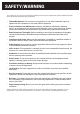
▪ efficiently and safely without creating a potential fire hazard.
▪ No structural material on the fryer or its flue chimney including physical alterations should be
made so it can be placed under an approved exhaust hood with fire protection.
▪ An 18” (46 cm) minimum clearance should be maintained between the flue vent and the
grease removal filters of the hood venting system.
▪ Never make flue connections directly between the fryer and exhaust hood.
▪ Do not obstruct the flow of the gases from the appliance. Proper air balance should be main-
tained in the room. The exhaust system must meet all applicable local air exchange require-
ments, regulations, ordinances, and building codes.
▪ Ensure that your ventilation system does not cause a down draft at the fryer’s flue opening.
Down draft will not allow the fryer to exhaust properly and will cause overheating, which may
cause permanent damage. Damage caused by down drafts aren’t covered under the equip-
ment warranty.
▪ Never allow anything to obstruct the flue or ventilation exiting from the fryer flue.
▪ NEVER put anything on top of the flue open area which may impact the exhaust gas flow.
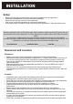
CONNECTION GAS:
All gas supply connections and any pipe joint compound must be resistant to the action of
propane gases or any other reasonable corrosion causes or catalysts.
▪ The gas inlet is located on the lower rear of the fryer. Codes require that a gas shutoff valve
be installed in the gas line ahead of the fryer. Installing the fryer and gas plumbing safely in
accordance with the local codes and manufacturer directives including an approved pressure
regulator is the purchaser’s (end user’s) responsibility not the fryer manufacturer or distribu-
tor.
▪ The gas supply line must be at least the equivalent of ½” (12.7 mm) iron pipe for single units
and 1-1/4” (31.75 mm) for batteries. If using the optional quick-disconnect flex hose, ¾” (19
mm) iron pipe feeding it is appropriate for single fryer applications.
▪ Each fryer is equipped with a ½” – ¾” coupling that facilitates the proper gas supply line
connection using approved piping and possibly an approved quick disconnect hose with its
required restraint cable hook-up to hold it in position that is required by code if on casters (a
mobile appliance set-up).
▪ Make sure the pipes are clean and free of obstructions, dirt, and piping compound. A battery
set up may require one or two connections of appropriate size for the gas requirement to
properly supply each gas cooking appliance in that battery line-up.
▪ Prior to lighting, check all joints in the gas supply line for leaks.
▪ Use soap and water solution. Do not use an open flame.
▪ After piping has been checked for leaks, fully purge gas pipes to remove any trapped air in
the line prior to bringing the fryer on line and into service.
GAS PRESSURE (ALL MODELS): Natural Gas, Town Gas or LP {Liquid Propane Gas}
▪ Set gas pressure at 4” W.C. (Water Column) for natural gas and 10” W.C. for LP gas.
▪ If incoming pressure exceeds ½ PSI, install an additional pressure regulator.
▪ The nameplate indicates the type of gas fuel supply (LP or Natural Gas).
▪ Gas piping should be performed by a licensed plumber and approved by local authorities.
TESTING THE GAS SUPPLY PIPING CONNECTION