® Superior Liquid Cooling Systems www.koolance.com RP-1250 User’s Manual English v1.
This User Manual is updated regularly. Please be sure to check our support page for a newer version of this guide: www.koolance.com/support GENERAL PRECAUTION Please read this manual carefully before beginning the installation of your Koolance system. This manual assumes the user has basic experience in building and configuring computer systems. Information referring to traditional hardware assembly is intentionally brief.
! WARNING: The Koolance liquid & coolant pack contain chemicals which may be harmful or fatal if swallowed. KEEP THIS AND ALL DANGEROUS CHEMICALS OUT OF THE REACH OF CHILDREN. If ingestion has occurred, seek medical attention immediately. Give two glasses of water. Do not induce vomiting. In the case of eye contact, flush eyes immediately with water for 15 minutes. Remove contact lenses. Call a physician if irritation persists.
Included Hardware - Temperature Sensors (x3) - ATX Pass-Thru Wire - Mounting screws - ATX Jumper Wire - User Manual Required Tools During installation, you may need the following tools: Chapter flat-head screw driver 1 System Features phillips-head screw driver pliers long-nose pliers scissors iv User Manual 1
Product Diagram Display Panel Reservoir ! CAUTION: This cooling system allows full user control of hardware safety settings, such as audio alarm, shutdown, and pump speed. Please be sure to configure your Display Panel properly, or damage to your computer, data, and/or equipment could result. The Koolance display panel allows control and monitoring of various aspects of the cooling unit. 4 buttons are used, with directional arrows to navigate or change settings, and a center button to enter/exit.
to 100% power. If any sensor reaches its set shutdown point, the system will shutdown power to the computer via relay using the “ATX pass-through” wire. ▲ TEMP1 TEMP2 ▼ TEMP3 55C 51C 60C 56C : Sensor #1, Alarm Point, Shutdown Point 54C : Sensor #2, Alarm Point, Shutdown Point 70C : Sensor #3, Alarm Point, Shutdown Point When in the “Temperature Settings” menu, the selected temperature sensor will to select a sensor to configure: flash.
The first line will flash. Press ▼ or ▲ to change what this line will display: PUMP SET ▲ The pump speed can be manually set from 1-10: PUMP(1-10) 7LV : Pump Speed Level The pump speed level will flash. Press ▼ or ▲ to adjust. Press previous menu. ◙ to return to the FLOW SET ▼ If a Koolance flow meter (sold separately) has been connected to the slot interface adapter, configuration is needed to properly display its values. Only one flow meter can be displayed by the cooling system.
◙ to The selected line will flash. Use ▼ and ▲ to navigate to other lines. Press enable or disable each value. This will remove the asterisk, thereby hiding that line from being shown on the main screen: ▲ *TEMP1 *TEMP2 *TEMP3 *FAN1 *FAN2 *FAN3 *PUMP ▼ *FLOW 21.7C : (shown) 21.2C : (shown) 20.8C : (not shown) 1770RPM : (shown) 1640RPM : (not shown) 1820RPM : (not shown) 5730RPM : (shown) 4.1LPM: (shown) Press ◄ to return to the previous menu, or press ► to exit DISPLAY SET.
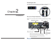
Positioning the Unit The cooling unit is designed to operate in one orientation. In other directions, the pump and reservoir may not bleed properly and could lead to cavitation. Chapter 2 YES NO Installation Reservoir & Pump Connections The rear of the unit accepts various connections to integrate with your cooling system. FAN: Radiator fan connections (2.0A max per plug, 4.
Power Connection ATX Pass-Through Lead The temperature sensors and ATX lead may come pre-connected to your unit. If not, connect them per the diagram on page 11. The ATX pass-through lead is responsible for sending the shut-down signal if any sensor reaches the preset shutdown temperature (See Display Panel for configuration). Attach the included power harness to the location on the rear of the unit marked “Power”. To this, connect a 12 Volt 4-pin Molex plug from your power supply.
Fittings Cooler & Tubing Configuration There are a vast number of methods for configuring a liquid cooling system (serial, parallel, combinations, alternating components, etc.). There is no single “correct” way! As long as coolant is flowing and you are satisfied with your device temperatures, it’s an acceptable configuration. Install the G 1/4 BSP threaded fittings you purchased for your unit. It’s recommended to hand-tighten all fittings to avoid damaging the unit.
Parallel Loops Disconnecting Hoses Parallel loops are normally used to help accommodate water blocks with significantly disproportionate flow restriction. They can become quite complicated and if not well-planned, may lower performance through added bottlenecks and pressure drop. One suggestion for parallel loops is to reduce tubing size when splitting. Ideally, the hose area going into the splitter will be roughly equal to (or slightly lower than) the combined hose area coming out.
Liquid Coolers You should now install the liquid coolers (CPU, GPU, Hard Drive, etc.) to your hardware before continuing this User Manual. Please refer to your cooler kit’s individual installation instructions, then continue on to the next section. With the connected outlet hose, roughly estimate the length you will need to your first cooler, and cut it. Cut the second hose with enough length to reach the last water block that will be in your system.
The cooling system should be powered on to assist in the filling process. This also allows you to check hose connections and make sure there are no tubing folds, leaks, or blockages. If cooling a computer, this can be done without powering on other hardware for extra safety (see below). Testing & Filling Once all the water blocks have been connected, the system can be filled with coolant. The fill port is located on top of the reservoir. Free this component by removing its side drive screws.
Adding Coolers & Maintenance Troubleshooting With normal use, Koolance’s liquid coolant should be replaced every 2-3 years. If it ever becomes contaminated, unclear, or significantly changes color, it should be replaced immediately. A Koolance “drain valve” (sold separately) is recommended to make that process easier. We hope your Koolance system will provide you with years of reliable cooling performance.
5. My system has boot-up problems, or does not turn on... Make sure the ATX wire lead is connected to “NO” (Normally Open) on the rear of the unit. (See: “Reservoir and Pump Connections” for details.) If this does not solve the issue, it is unrelated to the Koolance unit. In a computer, a problem with the RAM, motherboard, power supply, video card, processor, or monitor can cause the system to appear not to boot-up properly. 10. The flow meter reads “0”.
Limited Warranty Koolance Incorporated (“Koolance”) warrants each new Koolance liquid-cooled system (“the system”), against defects in materials or workmanship for a period of one year from the date of purchase, and agrees to repair or replace any defective Koolance system without charge. Shipping costs are non-refundable. This warranty is non-transferable. All warranty claims must be accompanied by the original proof of purchase.