TM Superior Liquid Cooling Systems UNIVERSAL MANUAL English v2.00 Protected by U.S. Patents 5,731,954; 6,234,240; 6,313,990 Other Technology Pending U.S.
This User Manual is updated regularly. Please be sure to check our support page for a newer version of this guide: www.koolance.com/support GENERAL PRECAUTION Please read this manual carefully before beginning the installation of your Koolance system. This manual assumes the user has basic experience in building and configuring computer systems. Information referring to traditional hardware assembly is intentionally brief.
! ! ! WARNING: The Koolance liquid & coolant pack contain chemicals which may be harmful or fatal if swallowed. KEEP THIS AND ALL DANGEROUS CHEMICALS OUT OF THE REACH OF CHILDREN. If ingestion has occurred, seek medical attention immediately. Give two glasses of water. Do not induce vomiting. In the case of eye contact, flush eyes immediately with water for 15 minutes. Remove contact lenses. Call a physician if irritation persists.
Table of Contents Introduction............................................................................................ 1 PC2 System Diagram ................................................................. 4 IPC System Diagram .................................................................. 5 Exos System Diagram .............................................................. 6 LED Display Panel ...................................................................... 7 Reservoir & Pumps ..................
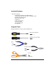
Included Hardware PC2 Series Systems: - motherboard standoffs & insulating washers - motherboard, slot card, 5.
1 Chapter Introduction User Manual 1
Congratulations on your purchase of a Koolance system! As the most sophisticated product of its kind, Koolance offers many unique features found nowhere else in the realm of computer cooling. In addition, you can expect to enjoy all of the advantages that water-cooling technology brings with it. Advantages of Water Cooling Water transfers 30 times faster, and holds over 4 times more heat than air.
The heart of a liquid cooling system is the pump. This device pushes liquid through each cooler and into the heat exchanger. Koolance systems use dual pumps to increase reliability and liquid pressure. If one pump should fail, the second can help prevent potential damage caused by heat increase. Every Koolance system includes built-in hardware safety features.
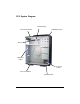
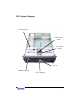
PC2 System Diagram Heat Exchanger Power Control Board LED Display Panel Air Duct 80mm Fan Holders Reservoir & Pumps Chassis Stabilizers Liquid Refill Tap 4 Introduction
IPC System Diagram Heat Exchanger Power Control Board Reservoir & Pumps Key Lock LED Display Panel Front USB Ports User Manual 5
Exos System Diagram Power Control Board Reservoir & Pumps Heat Exchanger LED Display Panel Power Connection Liquid Quick-Release Valves 6 Introduction
LED Display Panel The front control panel is a convenient display which will allow you to monitor liquid temperature, set the fan mode, and toggle temperature display settings (ºC or ºF). Mode 1 operates your system at 45% power until the temperature reaches 45ºC (113ºF), then increases to 100% power. Mode 2 operates your system at 45% power until the temperature reaches 35ºC (95ºF), then increases gradually to 100% at 40ºC (104ºF). Mode 3 runs the cooling system at 100% power.
Reservoir & Pumps The coolant tank includes many features which are distinctive to a Koolance system. It is also translucent for easy liquid-level monitoring. Dual pumps carry a flow rate of approximately 1030cc/min. Redundancy also provides higher system reliability; if one pump should fail, the other will maintain an acceptable temperature, or gradually bring the system to shut itself down (see LED Display Panel).
Heat Exchanger The heat exchanger, or radiator, is located beneath the fan cooling module. This is the primary cooling element, specifically designed for liquid cooling, and provides high thermal dissipation in a relatively small area. Inside, an aluminum mesh (Louver fin) is webbed between 13 horizontal liquid paths. Below the heat exchanger is a plastic Air Duct. This guide helps shield hardware from dust accumulation. It also directs airflow over the Power Control Board to assist with cooling.
Power Control Board Near the heat exchanger, the Power Control Board is responsible for a number of tasks, including: powering the pumps, LED display, heat exchanger fans, and operating the audio alarm and shutdown modes. CPU Temperature Probe LED Display 12V Power Supply Connection Heat Exchanger Fans ATX Power Switch Pass-Through Connections Pumps (NOTE: The Power Control Board connections and layout may vary depending on the system model.
(NOTE: Please skip to the next chapter if you have an Exos System) 2 Chapter Connecting PC2 & IPC Systems User Manual 11
Power Control Board You may begin the installation of your Koolance system by mounting a power supply in the chassis. The liquid cooling system requires approximately 8-10W from any standard ATX power supply. Connect a 12-volt 4-pin Molex plug from the power supply to the Power Control Board. Without this important connection, the Koolance system will NOT operate. ! 12 CAUTION: The Power Control Board is vital to system operation.
Cooler Arrangement The components in your Koolance system are connected in series. Each system contains a heat exchanger and reservoir, but you must choose which coolers you wish to install in between, for example: CPU Cooler, Motherboard Chipset Cooler, Video Chipset Cooler CPU Cooler, 2nd CPU Cooler, Video Cooler, Hard Drive Cooler Although it is possible to use up to eight (8) coolers in a Koolance system, a maximum of six (6) is recommended due to a reduction in liquid pressure.
Cutting Tube Lengths Before securely clamping the coolers, you must cut appropriate lengths of tubing to connect each device. It may be easier to temporarily lay your motherboard and video card inside the case to better estimate the required amounts. The system will come with two ends of tubing with which to attach your coolers. These tubes are already connected and clamped to the Heat Exchanger and Radiator.
Connecting Tubes Each cooler kit contains clamps to secure tubing to the cooler’s nozzles. Thread a clamp onto each tube before connecting it to the cooler nozzle. Attach by squeezing the tube while pushing firmly over the nozzle. The tubing should completely cover the nozzle. If you are finding it difficult to connect some tubes (such as to the CPU cooler), try temporarily stretching-out the tube end by inserting need-nose pliers.
Clamping After every cooler is connected, you may tighten the clamps to secure them. Clamping is done by positioning the reusable clamp just behind the cooler nozzle, and slowly applying pressure on the adjustment lobe with pliers until it locks. ! 16 CAUTION: The clamp should be tightened behind the widened portion of the cooler nozzle. Do not tighten a clamp over or on this nozzle section, as damage may occur to the cooler.
Disconnecting Inevitably, a connection will need to be undone, either because you are adding another cooler, or because something did not go properly during assembly. Be sure there is no liquid within the system before unclamping a component (see Draining for more information). Clamps can be unlocked by inserting a small flat screw driver into the center of the adjustment lobe and twisting. If done correctly, the clamp will snap open and can be used again.
(NOTE: Please skip to the next chapter if you have a PC2 or IPC System) 3 Chapter TM Connecting Exos Systems 18 Connecting Exos Systems
Positioning the ExosTM As an external unit, the Exos is designed to operate in various locations. Based on testing, Koolance has found the Exos to function adequately up to 10 meters (33 feet) away from most computers, depending on the system configuration and environment. (Excessive distance can lead to pump pressure drop and undesirable temperatures, however.) The Exos must be operated upright.
External Quick-Release Nozzles & Power Cable There are two segments of blue external tubing with your Exos system. You will need to install a white quick-release nozzle on one end of each. Thread a metal valve bolt over the end, and slide the tube over the narrow portion of the nozzle. Tighten the metal bolt by firmly screwing it to the plastic nozzle. Once completed, connect both quick-release nozzles and the external power cable to the Exos.
Slot Interface Adapter The Slot Interface Adapter allows the Exos to connect with any computer through an available card slot. It is responsible for both input and output tubes, along with the external power cable connection. This prevents the computer chassis from requiring any modifications. Install the Interface Adapter from the inside of the case, guiding the tension springs out the back of the slot. The Interface Adapter may be installed into any available rear card slot in your computer.
CPU Temperature Probe Case ATX Power Switch Motherboard Power Switch Optional Fan Connections Power Supply 4pin 12V Exos External Connection There are 4 main connections to the Slot Interface card which must be made. The Exos may appear to operate without some of these connections, but the hardware safety features will be deactivated. The Exos cooling system requires approximately 8-10W from any standard ATX power supply.
The black CPU temperature probe is the reading displayed by the front LED panel. You will position this thermal probe later during the installation of your CPU cooler. There are 2 power switch connections on the Slot Interface Card. Instead of connecting the chassis power switch to your motherboard, it will meet with a wire to the Slot Interface Adapter. Unplug the chassis ATX power switch lead from the motherboard. The power switch is typically labeled “PWRSW”, “PWSW”, or “PWBT”.
Cooler Arrangement The components in your Koolance system are connected in series. Each system contains a heat exchanger and reservoir, but you must choose which coolers you wish to install in between, for example: CPU Cooler, Motherboard Chipset Cooler, Video Chipset Cooler CPU Cooler, 2nd CPU Cooler, Video Cooler, Hard Drive Cooler Although it is possible to use up to eight (8) coolers in a Koolance system, a maximum of six (6) is recommended due to a reduction in liquid pressure.
Cutting Tube Lengths Before securely clamping the coolers, you must cut appropriate lengths of tubing with scissors to connect each device. If you are building a new computer system, it may be easier to temporarily lay the motherboard and CPU inside the case to better estimate the required amounts. The Exos external (blue) tubing connects to the first and last coolers in your system. Standard (clear) tubing is used in between each individual cooler.
Connecting Tubes Each cooler kit contains clamps to secure tubing to the cooler’s nozzles. Thread a clamp onto each tube before connecting it to the cooler nozzle. Attach by squeezing the tube while pushing firmly over the nozzle. The tubing should completely cover the nozzle. If you are finding it difficult to connect some tubes (such as to the CPU cooler), try temporarily stretching-out the tube end by inserting need-nose pliers.
Clamping After every cooler is connected, you may tighten the clamps to secure them. Clamping is done by positioning the reusable clamp just behind the cooler nozzle, and slowly applying pressure on the adjustment lobe with pliers until it locks. ! CAUTION: The clamp should be tightened behind the widened portion of the cooler nozzle. Do not tighten a clamp over or on this nozzle section, as damage may occur to the cooler.
Disconnecting Inevitably, a connection will need to be undone, either because you are adding another cooler, or because something did not go properly during assembly. Be sure there is no liquid within the system before unclamping a component (see Draining for more information). Clamps can be unlocked by inserting a small flat screw driver into the center of the adjustment lobe and twisting. If done correctly, the clamp will snap open and can be used again.
4 Chapter Installing Coolers User Manual 29
Chipset Cooler on a Motherboard The chipset cooler is used for both motherboard northbridge and video card chipsets. If installed, the motherboard must be partially removed from the chassis in order to install the chipset cooler. (The mounting screws are inserted from the back side of the board.) ! CAUTION: Removal of the original heatsink my void your manufacturer’s hardware warranty. Please consult the manufacturer if unsure, and keep all original parts in case of a return/RMA.
Remove the protective tape from the bottom of the chipset cooler. Through the original motherboard mounting holes, insert both plastic mounting screws from the back of the board. To help keep them secure, place rubber washers over the plastic screws from above the board. Use the metal attachment nuts to fasten the mounting bracket chipset to the motherboard. Hand-tighten all motherboard components.
CPU Cooler The most prominent liquid cooler is also the easiest to install. Apply thermal interface compound directly to the CPU die. Do not add more than is necessary to cover it with a very thin layer. Remove the protective film from the bottom of the CPU cooler. Insert the temperature sensor into either bottom groove on the CPU cooler. Apply metal tape to keep the temperature probe in place. Do not stick metal tape to the the raised (polished) portion of the CPU cold plate.
Assemble the CPU mounting bracket using the appropriate clips. The longer pair are for Intel P-4 processors; the shorter are for AMD Athlon/XP and Intel P-III processors. Clips for AMD socket 472 & P-III socket 370 Clips for P-4 socket 478 Fit the cooler and mounting brackets onto the CPU socket. The bracket clips slide inward and outward to hook to the socket. Check that the bracket clips are aligned before installing the tension screw.
! CAUTION: Installing the tension screw into the wrong cooler receptacle can cause insufficient cooler contact, and may result in hardware damage. AMD (left) Intel P4 AMD (right) Many processor dies are not equidistant from one edge of the socket to the other. For most AMD processors, the left or right receptacles will be used, depending on which direction the CPU socket faces. For Pentium-4 processors, use the center hole.
Chipset Cooler on a Video Card The chipset cooler is used for both motherboard northbridge and video card chipsets. If installed, the video card should be removed from the chassis in order to install the chipset cooler. (The mounting screws are inserted from the back side of the board.) ! CAUTION: Removal of the original heatsink my void your manufacturer’s hardware warranty. Please consult the manufacturer if unsure, and keep all original parts in case of a return/RMA.
Remove the protective tape from the bottom of the chipset cooler. Through the original mounting holes, insert both plastic mounting screws from the back of the video card. To help keep them secure, place rubber washers on the plastic screws above the board. If required, use the bracket extension tabs to reach the chipset’s mounting holes. The extensions are highly-adjustable for proper alignment. Use the metal attachment nuts to fasten the mounting bracket to the video card chipset.
Hard Drive Cooler Once mixed, the dual-pack of thermal encapsulate material will serve as the heat transfer pad between your drive and the cooling plate. It is not electrically conductive, and the material can be peeled-off after it has dried (after 60 hours). Hard drives may be used while the encapsulate is drying.
! CAUTION: Some hard drives have open spindle motors or other connections which encapsulate may interfere with. Tape should be placed over these areas before applying the thermal encapsulate. Using the mixing utensil, apply the encapsulate to the largest heat-producing components: the spindle motor and primary circuit chips on the bottom side of the drive. Use the included screws to mount the cooler over the encapsulate on the bottom side of the hard drive.
If you have a Koolance chassis, the hard drive cooler can be used with 2 hard drives. The second hard drive will require a “Second Hard Drive Kit” (purchased from your local Koolance dealer). First Hard Drive Thermal Encapsulate Install the Second Hard Drive Kit as you would a regular Cooler. Thermal encapsulate is applied to the drive, and the thin metal “Containment Plate” is screwed over it to the bottom of the hard drive.
5 Chapter Filling & Maintenance 40 Filling & Maintenance
Testing & Filling Your Koolance system is designed to automatically filter air from the liquid. Before filling, the cooling system should be “jump-started” to assist in the circulation process. Make sure the AC power cord is attached to the power supply. If the power supply has a rear switch, it must be in the ON (-) position. Using the ATX Jumper Wire, insert the metal prongs into pin numbers 4 and 6 on the 20-pin motherboard ATX power supply connector (green and a black ground wire-- See diagram).
! WARNING: The liquid coolant is electrically conductive. Use caution when filling the system, and keep all liquids away from computer hardware and power cables. In case of emergency during installation, immediately unplug the computer’s rear power cable. Dry the system thoroughly before proceeding. Cut a small corner in the coolant pack, and slowly fill the reservoir. You will probably not need the entire amount of liquid. The reservoir should be filled up to the “Refill” indicator arrow.
! CAUTION: Positioning of Exos systems during liquid filling is important. The Exos must be higher than all internal cooling components, or coolant will exit the refill tap upon filling. Because of gravity, the Exos must be placed above all internal cooling components while being filled. Otherwise, coolant will exit the refill tap once the reservoir is full.
Draining & Maintenance The liquid coolant in your system should be emptied for any of the below reasons: 1. To Keep it Clean - Koolance recommends replacing the liquid coolant once every 12 months. The coolant should also be replaced if it becomes contaminated or significantly changes color. 2. Upgrading Coolers - Whether you are adding or removing liquid coolers, upgrades can be performed more easily with a dry system. 3.
Troubleshooting We hope your Koolance system will provide you with years of reliable cooling performance. To help avoid unnecessary RMA issues, we have prepared this list of possible operational problems, and their most common solutions. 1. How do I tell if the pumps are working?... After inital air-filtering, the pumps may not create enough noise to tell if they’re working properly.
4. After the system has been on for awhile, the temperature alarm sounds... Make sure that the LED temperature reads at least 50ºC (122ºF) or higher while the alarm is sounding; if not, the audio alarm may in fact be your motherboard’s BIOS alarm. If the system is not exhibiting signs of overheating (see #2 in Troubleshooting), this temperature monitor may need to be disabled to ignore false readings by BIOS. The Koolance LED Display will flash “FLT” (fault) whenever the cooling system alarm sounds.
6. My system appears to be leaking fluid... Since users are allowed to configure their own coolers and clamps, it is possible a connection was not properly sealed (however unlikely). If you can see liquid somewhere on the tubing, or at the bottom of the chassis, computer components may need to be removed for a system test (see Flow Testing). If liquid should get onto another computer component, shut down the system, and remove the component. In most cases, the hardware will be fine after allowing it to dry.
Limited Warranty Koolance Incorporated (“Koolance”) warrants each new Koolance liquid-cooled system (“the system”), against defects in materials or workmanship for a period of one year from the date of purchase, and agrees to repair or replace any defective Koolance system without charge. Shipping costs are non-refundable. This warranty is non-transferable. All warranty claims must be accompanied by the original proof of purchase.
www.koolance.