VM62(A) / VM42(A) User’s Manual Preface VM62(A) / VM42(A) Intelligent Universal Controller Modules for Stand-Alone and VMEbus Manual Order No. 3368 User’s Manual Issue 3 Unpacking and Special Handling Instructions This PepCard product is carefully designed for a long and fault-free life; nonetheless, its life expectancy can be drastically reduced by improper treatment during unpacking and installation. Observe standard anti-static precautions when changing piggybacks, ROM devices, jumper settings, etc.
Preface VM62(A) / VM42(A) User’s Manual R EVISION HISTORY VM62(A) / VM42(A) User’s Manual Issue 1 2 2.0.1 3 Brief Description of Changes Issue 1 General Corrections throughout Manual Correction of Figure 3.2.0.1 (Jumper Layout Solder Side) Updated for board index 02 PCB Index 01-01/2 01-01/4 01-01/4 02 Date of Issue March, 1995 June, 1995 July, 1995 December, 1995 This document contains proprietary information of PEP Modular Computers.
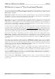
VM62(A) / VM42(A) User’s Manual Preface PEP Modular Computers® Two Year Limited Warranty We grant the original purchaser of PEP products the following hardware and system warranty. No other warranties that may be granted or implied by anyone on behalf of PEP are valid unless the consumer has the express written consent of P E P Modular Computers.
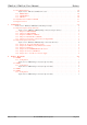
Preface VM62(A) / VM42(A) User’s Manual T ABLE OF CONTENTS Page 1. Introduction . . . . . . . . . . . . . . . . . . . . . . . . . . . . . . . . . . . . . . . . . . . . . 1-1 1.1 Product Overview . . . . . . . . . . . . . . . . . . . . . . . . . . . . . . . . . . . . . . . . . . . . . . . . . . . . . . . . 1 1.2 Ordering Information . . . . . . . . . . . . . . . . . . . . . . . . . . . . . . . . . . . . . . . . . . . . . . . . . . . . . . 2 Figure 1.2.0.1: VM62(A)/VM42(A) Configuration Options . . . . . .
VM62(A) / VM42(A) User’s Manual Preface 2.7 Front Panel Functions . . . . . . . . . . . . . . . . . . . . . . . . . . . . . . . . . . . . . . . . . . . . . . . . . . . . . Figure 2.7.0.1: LED Port and Button Location . . . . . . . . . . . . . . . . . . . . . . . . . . . . . . . . . . 2.7.1 RESET Button . . . . . . . . . . . . . . . . . . . . . . . . . . . . . . . . . . . . . . . . . . . . . . . . . . . . . 2.7.2 ABORT Button . . . . . . . . . . . . . . . . . . . . . . . . . . . . . . . . . . . . . . . . .
Preface VM62(A) / VM42(A) User’s Manual 5. Pinouts . . . . . . . . . . . . . . . . . . . . . . . . . . . . . . . . . . . . . . . . . . . . . . . . 5-1 5.1 Main Board . . . . . . . . . . . . . . . . . . . . . . . . . . . . . . . . . . . . . . . . . . . . . . . . . . . . . . . . . . . . 1 Figure 5.1.0.1: Main Board Connector Overview . . . . . . . . . . . . . . . . . . . . . . . . . . . . . . . . 1 5.1.1 VMEbus Connector (ST1) . . . . . . . . . . . . . . . . . . . . . . . . . . . . . . . . . . . . . . . .
VM62(A) / VM42(A) User’s Manual Chapter 1 Introduction 1 1. INTRODUCTION 1.1 Product Overview The computer user today requires high performance to meet high expectations. At the same time, the mass of data that has to be processed is dramatically increasing, for instance the data that a modern graphic user interface generates. Additionally, there is a further demand on the communications ability and multi-functionality of the computer.
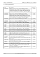
Chapter 1 Introduction VM62(A) / VM42(A) User’s Manual 1.2 Ordering Information Name Description VM62-BASE VMEbus single board computer comprising MC68060 @ 50 MHz, MC68EN360 @ 25 MHz, 256 kByte dual-ported SRAM (with Gold Cap for backup), configured for use with the AutoBahn interface piggyback, up to 6 serial interfaces (2 available on the front panel as RS232 and an additional 4 divided between the CXC interface and SI-Interface), CXC Interface, PEPbug. 12349 VM62-BASE Same as order no.
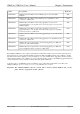
VM62(A) / VM42(A) User’s Manual Chapter 1 Introduction Name Description Order No CXM-SIO3-1 CXM module with 3 RJ45 connected RS232 ports for use with a CXC backplane TBD CXM-SIO3-1 CXM module with 3 RJ45 connected RS232 ports, compatible for direct connection to a CPU board 13692 CXM-SIO3-2 CXM module with 2 RJ45 connected SC piggyback ports and one SI piggyback interface, no front panel (delivered with SC piggyback) for use with a CXC backplane TBD CXM-SIO3-2 CXM module with 2 RJ45 connected
Chapter 1 Introduction VM62(A) / VM42(A) User’s Manual OR SRAM 1 MByte RTC VM62(A) MC68060 @ 50 / 66MHz VM42(A) MC68040V @ 33 MHz MC68EN360 @ 33 MHz VM62(A) MC68060 @ 50/66 MHz MC68EN360 @ 25 /33MHz SRAM 256 kByte OR dual-ported SRAM MP interface (optional) Spanciever Dual-ported SRAM 128 kByte DRAM + FLASH VMEbus * System controller * Master/slave interface SRAM 1 MByte SRAM 256 kByte OR SRAM 1 MByte CPU Options Page 1-4 VM42(A) MC68040(V) MC68040 @ 33 MHz 1 kbit EEPROM Optional MP Interf
VM62(A) / VM42(A) User’s Manual 1.3 Chapter 1 Introduction Specifications Main CPU I/O Controller MC68060 MC68040 MC68040V MC68LC040 66 or 50 MHz 33 or 25 MHz 33 or 25 MHz 33 or 25 MHz (3.3V) (3.3V) MC68EN360, 25 or 33MHz used in companion mode Memory DRAM FLASH SRAM EEPROM 1, 4, 16 or 32 Mbyte 0.
Chapter 1 Introduction I/O Ports Serial Mezzanine Interface VM62(A) / VM42(A) User’s Manual RISC controller (in the 68EN360) with 14 dedicated DMA channels 4*multiprotocol SCCs up to 8 MBaud with one (two) supporting IEEE 802.
VM62(A) / VM42(A) User’s Manual 1.4 Chapter 1 Introduction Features CPU Options The Table below illustrates the capabilities of the available CPUs. The 68060 processors operating at 50 MHz deliver up to 100 MIPs while the 68040 processors operating at 33 MHz give performances up to 35 MIPs. Table 1.4.0.1: CPU Configuration * Processor Product CPU MMU FPU Supply MC68040 VM42(A) √ √ √ 5V MC68LC040* VM42(A) √ √ 5V MC68040V VM42(A) √ √ 3.
Chapter 1 Introduction VM62(A) / VM42(A) User’s Manual Ethernet Interface (SI-10B2, SI-10B5, SI-10BT) Three different piggybacks complete with all the associated control logic are available providing 10Base5, 10Base2 or 10BaseT interfaces. Note The SI-10B5 piggyback requires an external +12V power source to operate. Fieldbus Interface (SI-PBPRO) This is a fully optoisolated RS485 (PROFIBUS) interface piggyback with a 9-pin D-Sub connector.
VM62(A) / VM42(A) User’s Manual 1.5 Chapter 1 Introduction Related Publications VITA VMEbus Specifications Revision C1 MPI: Modpack and CXC Specification from PEP (Version 1.
VM62(A) / VM42(A) User’s Manual Chapter 2 Functional Description 2 2. FUNCTIONAL DESCRIPTION Figure 2.0.0.1: VM62(A) / VM42(A) Block Diagram CPU 68(LC)040 68040V 33 / (40) MHz 68060 50 / 66 / (80) MHz 32 Bit 32 Bit 68EN360 Companion Mode 25/33/(40) MHz DRAM 1/4/16/32 MB FLASH 0.5/1/2/4 MB IRQ Handler Clock Logic Reset Logic Status/ Control Logic Watchdog Address/ Data/ Control 3.
Chapter 2 Functional Description VM62(A) / VM42(A) User’s Manual 2.1 The 68EN360 (QUICC) on the VM62(A) / VM42(A) Motorola’s MC68EN360 is a 32 bit high performance communication controller, combining powerful peripheral functions with system integration functions and an on-chip microprocessor core (CPU32+). On the VM62(A) / VM42(A), the on-chip CPU core is disabled and replaced with a more powerful external CPU, the MC68040 or MC68060.
VM62(A) / VM42(A) User’s Manual Chapter 2 Functional Description 2.2.3 Primary Address Decoder The primary address decoder generates the following select signals. CS_360 Secondary address decoder (68EN360, DRAM, FLASH) CS_VME VMEbus address range CS_AUT AutoBahn Interface address range CS_BSS Bussizer address range (VME, SRAM, AutoBahn, I/O) BERR_0 Reserved address range (Bus Error) EN_BSS 68EN360 DMA address range IACK Interrupt Acknowledge Cycle 2.2.
Chapter 2 Functional Description 2.2.5 VM62(A) / VM42(A) User’s Manual Address Map The VM62(A) / VM42(A) address map shown in the Table below is based on the recommended default initialisation of the 68EN360 chip select logic. Figure 2.2.5.
VM62(A) / VM42(A) User’s Manual 2.2.6 Chapter 2 Functional Description DMA Transfers Memory to memory transfers with the 68EN360 DMAs are possible with any combination of on-board and VME addresses. In order to achieve address compatibility between CPU/VME and DMA/VME transfers, it is recommended that the initialisation of CS2 be initialised to the standard VME address space as described in the Software Configuration chapter in this manual. 2.
Chapter 2 Functional Description 2.3.3 VM62(A) / VM42(A) User’s Manual Mailbox Interrupt An external VMEbus master may interrupt the VM62(A) / VM42(A) by setting P_IRQ5 (pending mailbox IRQ) in the VME control / status register. The address of this dual-ported register seen from VME is identical to the base address of the dual-ported SRAM, occupying the lower 8 kBytes (odd byte addresses) of the dual-ported SRAM. Setting P_IRQ5 generates an autovector 5 interrupt on the CPU.
VM62(A) / VM42(A) User’s Manual Chapter 2 Functional Description BADR [3 .. 0] VME Board Base Address 0000 0001 0010 0011 0100 0101 0110 0111 1000 1001 1010 1011 1100 1101 1110 1111 $00 00 00 $10 00 00 $20 00 00 $30 00 00 $40 00 00 $50 00 00 $60 00 00 $70 00 00 $80 00 00 $90 00 00 $A0 00 00 $B0 00 00 $C0 00 00 $D0 00 00 $E0 00 00 $F0 00 00 2.
Chapter 2 Functional Description VM62(A) / VM42(A) User’s Manual 2.4.
VM62(A) / VM42(A) User’s Manual Chapter 2 Functional Description 2.5 I/O Ports 2.5.1 Ethernet Port The MC68EN360 is specified to support a full set of IEEE 802.3/Ethernet CSMA/CD media access control and channel interface functions. Since the 68EN360 requires an external interface adapter and transceiver function, the Ethernet port can be adapted to all standard Ethernet functions, such as 10BaseT, 10Base5 and 10Base2 via a piggyback connected to the SI Interface on the VM62(A) / VM42(A). 2.5.
Chapter 2 Functional Description VM62(A) / VM42(A) User’s Manual The Ethernet port can be configured via the SI Interface with 10BaseT, 10Base5 or 10Base2 SI Modules. The following configurations are therefore possible for the serial ports.
VM62(A) / VM42(A) User’s Manual Chapter 2 Functional Description Table 2.5.3.
Chapter 2 Functional Description VM62(A) / VM42(A) User’s Manual CXC Function Pin Nr. 68302 HW Compatible 68(EN)360 Port IRQ_1 a1 Yes PC0 IRQ_2 a2 Yes PC1 IRQ_3 a3 Yes PC2 IRQ_4 a4 Yes PC3 CXC Function Pin Nr. 68302 HW Compatible 68(EN)360 Port DMA_ACK c2 Yes PB5 DMA_REQ c3 Yes PB4 CXC Function Pin Nr.
VM62(A) / VM42(A) User’s Manual Chapter 2 Functional Description CXC Function Pin Nr.
Chapter 2 Functional Description VM62(A) / VM42(A) User’s Manual Notes Reserved Pins 1) On a standard VM62(A)/VM42(A) board, these signals are already used for UART ports at BU7 and BU8. 2) On a standard VM62(A)/VM42(A) board, these signals are used for SPI to which the EEPROM is already connected. PB0 is chip select of the EEPROM. 3) On PA13, a 24 MHz clock signal is routed via jumper J6. This signal is always needed for PEP standard software (serial drivers).
VM62(A) / VM42(A) User’s Manual Chapter 2 Functional Description Table 2.5.3.
Chapter 2 Functional Description VM62(A) / VM42(A) User’s Manual Group Signal Name Mneumonic Function SI SI Receive Data L1RXDA, L1RXDB Serial input to the Time Division Multiplexed (TDM) channel A or channel B SI Transmit Data L1TXDA, L1TXDB Serial output from the TDM channel A or channel B SI Receive Clock L1RCLKA, L1RCLKB Input receive clock to TDM channel A or channel B SI Transmit Clock L1TCLKA, L1TCLKB Input transmit clock to TDM channel A or channel B SI Transmit Sync Signals L1TS
VM62(A) / VM42(A) User’s Manual 2.6 Special Functions 2.6.1 Real-Time Clock Chapter 2 Functional Description The RTC (V3021 3-wire serial interface) is a 1-bit device which is accessible over the CS6 of the 68EN360. Its timekeeping features include :• seconds, minutes, hours, day of month, month, year, week day and week number in BCD format. • leap year and week number correction • standby supply smaller than 1µA See also the Software Configuration chapter in this manual and the V3021 data sheet. 2.6.
Chapter 2 Functional Description VM62(A) / VM42(A) User’s Manual Note During VMEbus cycles, the on-board bus error timer is reset as soon as the VM62(A) / VM42(A) gains VMEbus ownership. This means that the time gap between a VMEbus request and the starting of the VMEbus cycle is monitored by the on-board BERR timer. VMEbus cycles themselves are monitored by the separate VMEbus BERR timer (BUS monitor). 2.6.5 VME Bus Error Timer The VM62(A) / VM42(A) also provides a bus monitor for the VMEbus.
VM62(A) / VM42(A) User’s Manual 2.6.8 Chapter 2 Functional Description Board Control/Status Register Address: Format: Access: Value after HW reset: CS7 + $7 Byte read / write 0 7 CS7 + $7 WDG PEP Default Address $CD 00 00 07 6 5 4 BERR2 BERR1 EN_WDG 3 2 TR_WDG EN_BERR1 1 0 ACFAIL LED_G Register Description Name Value Access Description WDG bit 7 Read/Write Set by watchdog timer when timout has been reached.
Chapter 2 Functional Description 2.6.9 VM62(A) / VM42(A) User’s Manual Reset Sources Reset Source Identification Push button No SYSRES* VME No Watchdog WDG bit on-board (Board Control/Status Register) Power monitor (4.65V) Inside the 68EN360 2.7 Front Panel Functions Figure 2.7.0.1: LED Port and Button Location Watchdog LED Yellow General Purpose Green CPU HALT or RESET Red U W H RESET Switch 2.7.
VM62(A) / VM42(A) User’s Manual Chapter 2 Functional Description 2.8 Data Retention for RTC and SRAM Short term data retention for RTC and SRAM is gained with two Gold-Caps, each with a value of 0.22 Farad. In contrast to Lithium cells, Gold-Caps do not require servicing. This short term backup is intended for short power failures or for reconfiguring systems.
Chapter 2 Functional Description 2.
VM62(A) / VM42(A) User’s Manual May 17, 1996 Chapter 2 Functional Description © 1995 PEP Modular Computers Page 2-23
VM62(A) / VM42(A) User’s Manual Chapter 3 Configuration 3 3. CONFIGURATION The VM62(A) / VM42(A) has twelve jumpers fitted to the board. The list of default jumper settings is shown below. Table 3.0.0.
Chapter 3 Configuration 3.1 VM62(A) / VM42(A) User’s Manual Jumper Description (Component Side) Figure 3.1.0.
VM62(A) / VM42(A) User’s Manual 3.1.1 Jumper J1: VME-SYSCLK Setting Description Set SYSCLK connected to VME Open SYSCLK disconnected from VME 3.1.2 Description Set On-board RESET generator to VME Open On-board RESET disconnected from VME Default Jumper J8: VME Boot (VBOOT) Setting Description Set Boot from VME enabled Open Boot from VME disabled 3.1.4 Default Jumper J2: VME-SYSRES Setting 3.1.
Chapter 3 Configuration 3.2 VM62(A) / VM42(A) User’s Manual Jumper Description (Solder Side) Figure 3.2.0.1: VM62(A) / VM42(A) Jumper Layout (Solder Side) J133 J131 3 1 2 J134 J6 J5 J4 J3 J10 J132 3 1 2 J7 J11 J12 WARNING! Solder jumpers are factory set and must not be altered by the user. Alteration of jumper settings can result in damage to the board (especially J131-134).
VM62(A) / VM42(A) User’s Manual 3.2.1 Jumpers J3, J4 and J5: CPU (Bus) Clock Setting J3 J4 J5 Set Set Open 25 MHz Open Set Open 33.3 MHz Set Open Open 40 MHz 3.2.2 Chapter 3 Configuration Description Jumper J6: 24 MHz Clock (Communications Clock) Setting Description Set Clock connected to 68EN360 Open Clock not connected to 68EN360 Default Note Jumper J6 must be opened if the RCLK2 signal (CXM pin c16) is required, as it is not compatible with PEP standard software. 3.2.
Chapter 3 Configuration 3.2.6 VM62(A) / VM42(A) User’s Manual Jumpers J131 - J134: Processor Power Supply Setting J131 - J134 Description 1-2 5 Volt (68040 / 68LC040) 1-3 3.3 Volt (68040V / 68060) WARNING! Alteration of the settings of J131-J134 can result in damage to the board.
VM62(A) / VM42(A) User’s Manual Chapter 4 Memory Piggybacks 4 4. MEMORY PIGGYBACKS 4.1 DM600 4.1.1 Configuration The DM600 is a memory piggyback fitted with 4MByte DRAM and either 1 or 4MByte Flash EPROM. Two configurable jumpers are present on the board, indicating if write protection is enabled or disabled and whether 1MBit or 4MBit Flash EPROM chips are fitted. Figure 4.1.1.
Chapter 4 Memory Piggybacks VM62(A) / VM42(A) User’s Manual Jumper J2: Flash Chip Size Setting Description 1-2 4 Mbit Flash chips fitted 1-3 1 Mbit Flash chips fitted 4.2 DM601 4.2.1 Configuration The DM601 is a memory piggyback fitted with 16MByte DRAM and either 1 or 4MByte Flash EPROM. Two configurable jumpers are present on the board, indicating if write protection is enabled or disabled and whether 1MBit or 4MBit Flash EPROM chips are fitted. Figure 4.2.1.
VM62(A) / VM42(A) User’s Manual Chapter 4 Memory Piggybacks Jumper J2: Flash Chip Size Setting Description 1-2 4 Mbit Flash chips fitted 1-3 1 Mbit Flash chips fitted 4.3 DM602 In preparation 4.4 DM603 4.4.1 Configuration The DM603 is a memory piggyback fitted with 32MByte DRAM and 0.5MByte Flash EPROM. A version of the DM603 with 2MByte Flash EPROM fitted will soon be available. One configurable jumper is located on the board, indicating whether the Flash EPROMs are write protected.
Chapter 4 Memory Piggybacks VM62(A) / VM42(A) User’s Manual This page has been intentionally left blank Page 4-4 ©1995 PEP Modular Computers May 17, 1996
VM62(A) / VM42(A) User’s Manual Chapter 5 Pinouts 5 5. PINOUTS 5.1 Main Board Pin 7 ST3A ST3B ST3C Figure 5.1.0.
Chapter 5 Pinouts 5.1.1 * VM62(A) / VM42(A) User’s Manual VMEbus Connector (ST1) Pin Nr.
VM62(A) / VM42(A) User’s Manual 5.1.2 Chapter 5 Pinouts CXC Connector (ST3) For CXC connector pinouts, please refer to the CXC Appendix. 5.2 Front Panel The front panel connectors are dependent on which interface piggyback is mounted. They are: Standard Connectors • 2 * RS232 serial interfaces (BU7 and BU8).
Chapter 5 Pinouts 5.2.1 VM62(A) / VM42(A) User’s Manual Standard RS232 Connectors Figure 5.2.1.1: Standard Front Panel Pinouts Dependent on version ordered Watchdog LED Yellow General Purpose Green CPU HALT or RESET Red U W H ABORT Button AB SER 0 RST Pin 1 TERM RESET Button Pin 1 BU7 RJ12 (SMC1) Pin 6 BU8 RJ12 (SMC2) Pin 6 VMx2(A) 6-pin RJ12 RS232 Serial Interface Connectors (BU7 and BU8) Pin Nr.
VM62(A) / VM42(A) User’s Manual 5.2.2 Chapter 5 Pinouts Ethernet 10Base2 (SI-10B2) SITB2 on board Figure 5.2.2.
Chapter 5 Pinouts 5.2.3 VM62(A) / VM42(A) User’s Manual Ethernet AUI / 10Base5 (SI-10B5) SITB5 on board Pin 1 Pin 8 ETHERNET 10Base5 Figure 5.2.3.1: SI-10B5 Front Panel Pinouts Pin 9 BU3 (SCC1) Pin 15 15-pin D-Sub Ethernet AIU / 10Base5 Connector (BU3) Pin Nr.
VM62(A) / VM42(A) User’s Manual 5.2.4 Serial RS232 Interface (SI-PB232) Chapter 5 Pinouts SI232 on board Pin 1 Pin 8 Pin 1 SER 2 Pin 8 BU2 RJ45 (SCC1) SER 1 Figure 5.2.4.1: SI-PB232 Front Panel Pinouts BU3 RJ45 (SCC4) 8-pin RJ45 Serial Interface Connectors (BU2 and BU3) Pin Nr.
Chapter 5 Pinouts 5.2.5 VM62(A) / VM42(A) User’s Manual Ethernet 10BaseT (SI-10BT) SITBT on board Figure 5.2.5.1: SI-10BT Front Panel Pinouts Collision Col Tx Transmit ETHERNET 10BaseT Pin 8 Pin 1 BU3 RJ45 (SCC1) 8-pin RJ45 Serial Interface Connector (BU3) Pin Nr. Signal 1 TD+ 2 TD- 3 RD+ 4 Not Connected 5 Not Connected 6 RD- 7 Not Connected 8 Not Connected Configuration The SI-10BT piggyback has one configurable jumper that sets the shielding of the board.
VM62(A) / VM42(A) User’s Manual 5.2.6 Chapter 5 Pinouts PROFIBUS Interface (SI-PBPRO) SIPRO on board Pin 1 BU3 (SCC1) Pin 5 PROFIBUS Figure 5.2.6.1: SI-PBPRO Front Panel Pinouts Transmit Yellow Pin 6 Pin 9 Tx 9-pin D-Sub PROFIBUS Connector (BU3) Pin Nr. Signal Description 1 SHIELD Shield, Protective Ground resp.
Chapter 5 Pinouts VM62(A) / VM42(A) User’s Manual This page has been intentionally left blank Page 5-10 ©1995 PEP Modular Computers May 17, 1996
VM62(A) / VM42(A) User’s Manual Chapter 6 Software Configuration 6 6. SOFTWARE CONFIGURATION 6.1 Initializing the 68EN360 Many components of the VM62(A) / VM42(A) are controlled by the MC68EN360. Due to this fact, this chip requires a special initialization sequence before any other software can be started. The following list describes how the initialization must be performed on the VM62(A) / VM42(A).
Chapter 6 Software Configuration 7) 8) 9) VM62(A) / VM42(A) User’s Manual Configure CLK lines • COM2 to full strength • COM1 disabled • register access locked 0x83.B -> CLKOCR Configure PEPAR register • set /IOUT0-2 are PRTY0-2 • select /RAS1DD function • select /WE0-3 • select AMUX • select /CAS0-3 0x51C0.W -> PEPAR Configure GMR register • set refresh counter period to 24 • set refresh cycle length to 3 • set DRAM port size to 32 bit • assert CS/RAS on CPU space • enable refresh 0x18800100.
VM62(A) / VM42(A) User’s Manual Chapter 6 Software Configuration 12) The system software normally determines the real sizes of the DRAM and SRAM installed and re-programs the CS lines accordingly. The simplest way to achieve this is to write a pattern to the first location and then search for that pattern at meaningful distances (e.g. 256kB, 512 kB, 1 MB, 2 MB, 4 MB, 8 MB, 16 MB).
Chapter 6 Software Configuration VM62(A) / VM42(A) User’s Manual Address List of Involved Registers MBAR 0x3FF00 RSR SYPCR MCR PLLCR CDVCR CLKOCR PEPAR GMR AVR BR0 OR0 BR1 OR1 BR2 OR2 BR3 OR3 BR4 OR4 BR5 OR5 BR6 OR6 BR7 OR7 0xC0001009 0xC0001022 0xC0001000 0xC0001010 0xC0001014 0xC000100C 0xC0001016 0xC0001040 0xC0001008 0xC0001050 0xC0001054 0xC0001060 0xC0001064 0xC0001070 0xC0001074 0xC0001080 0xC0001084 0xC0001090 0xC0001094 0xC00010A0 0xC00010A4 0xC00010B0 0xC00010B4 0xC00010C0 0xC00010C4 CICR SD