
Owner's manual


KTD-S0003-C Page 27 CPLD Interface
pITX-SP Software Guide
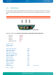
6.2.4 GPIO IRQ Example
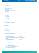
It's very simple to check the interrupt feature. The picture shows how the jumper must be set. For testing
remove a jumper (breaks IRQ generation) and set it again. The interrupt assignment to IRQ7 is not change-
able.
Attention: Set the entry Advanced/Onboard DeviceConfiguration/Chipset Configuration/Serial IRQ Mode to Continuous.
J3202
J3201
J1800
Jum
p
er
BIOS Setup settings (entry Advanced/Onboard Device Configuration/GPIO Configuration):
GPIO Pin 0 IRQ Input
GPIO Pin 1 IRQ Input
GPIO Pin 5 Output
GPIO Pin 6 Output
Default Output State High
#include <conio.h>
#include <stdio.h>
#include <dos.h>
#define CPLD_BASE_ADDR 0xA80
#define GPIO_CONTROL 0x9F
#define GPIO_INPUT 0XA0
#define GPIO_OUTPUT 0xA1
#define GPIO_IRQ_POLARITY 0xA7
#define IRQ_FALLING_EDGE 0x00
#define IRQ_ENABLE 0x08
#define IRQ_BIT5 0x20
#define IRQ_BIT6 0x40
#define IRQ_TIMEOUT 10000
#define VECTOR_IRQ7 15
#define CTRL_8259 0x20
#define IMR_8259 0x21
#define EOI 0x20
#define IRQ_MASK 0x80 // Mask for IRQ7
#define __CPPARGS