
Owner's manual

KTD-S0003-C Page 21 CPLD Interface
pITX-SP Software Guide
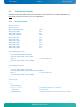
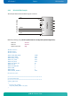
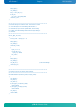
6.2.3 I2C with GPIOs Example
This example demonstrates the GPIO usage as an I2C bus.
V
DD
INT
A0
A1
A2
SCL
SDA
V
SS
P0
P1
P2
P3
P4
P5
P6
P7
PCF8574
GPIO0
GPIO4
GND
VCC
D
i
g
ital I
/
O
I
n
ter
f
ace
N.C.
BIOS Setup settings (entry Advanced/Onboard Device Configuration/GPIO Configuration):
GPIO Pin 0 Tri-State
GPIO Pin 4 Tri-State
Default Output State High
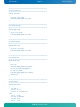
#include <conio.h>
#include <dos.h>
#include <stdio.h>
#define CPLD_BASE_ADDR 0xA80
#define GPIO_INPUT 0xA0
#define GPIO_OUTPUT 0xA1
#define I2C_CLOCK 0x10
#define I2C_DATA 0x01
#define I2C_DELAY_VAL 50
#define I2C_OK 0
#define I2C_ERR_NAK 1
#define TRUE 1
#define FALSE 0
#define DEVICE_PCF8574 0x40
int i2c_bits, i2c_error;
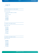
//*********************************************************
//* Sets clock line high
//*********************************************************
void SCL_High (void)
{
i2c_bits |= I2C_CLOCK;
outp (CPLD_BASE_ADDR+1, i2c_bits);
}