
Owner's manual
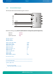

KTD-S0003-C Page 18 CPLD Interface
pITX-SP Software Guide
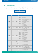
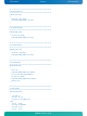
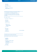
0xF4 RW
0x3F
1)
Fan control register
Bit 0 - 4 Fan output value
Bit 5 Reserved
Bit 6 - 7 Fan divisor
00 = divisor = 1
10 = divisor = 2
01 = divisor = 4
11 = divisor = 8
0xF5 RO ---
Fan speed register
Bit 0 - 7 Fan speed
Note: 1) Default Setup settings.
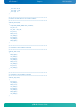
6.1 Special Hints
The following remarks must be considered (especically the first hint).
6.1.1 Reserved Bits
Every bit which is marked as Reserved may not be changed (exception: watchdog control). These bits must
be masked. Not observing this hint can in the worst case lead to system crashes, e.g. after a warm boot.
6.1.2 GPIO Input Register
The input register reflects the status of the pins which are defined as output. Example: if GPIO7 defined as
an output the GPIO7 bit in the input register reads back low level when the output has low level and a high
level when the output has high level.
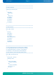
6.1.3 Fan Divisor
The base time for the divisor is 1 second (divisor = 1). To calculate the fan speed in rounds per minute
(rpm) the speed value must be multiplicated by 60. Increasing the divisor leads to smaller base times (0.5
seconds and so on).