
Owner's manual

KTD-S0003-C Page 17 CPLD Interface
pITX-SP Software Guide
6 CPLD Interface
Various functions are implemented in the CPLD: e.g. watchdog, digital I/O and fan control. Access to the
CPLD register is via an index-data register pair using only two I/O byte locations (fixed addresses).
Index Register Data Register
0xA80 0xA81
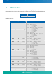
Register overview:
Index Type Reset Function
0x00 RO --- CPLD version
0x9F RW
0x81
1)
GPIO control register
Bit 0 GPIO control
0 = disabled
1 = enabled
Bit 1 Autostart jumper status (RO)
Bit 2 Autostart function
0 = do nothing
1 = restart
Bit 3 GPIO interrupt control
0 = disabled
1 = enabled
Bit 4 Reserved
Bit 5 Reserved
Bit 6 Wake on LAN control (State S5)
0 = enabled
1 = disabled
Bit 7 Reserved
0xA0 RO
0x0F
1)
GPIO input register
Bit 0 = GPIO0 ... Bit 7 = GPIO7
0 = low level
1 = high level
0xA1 RW
0x00
1)
GPIO output register
Bit 0 = GPIO0 ... Bit 7 = GPIO7
0 = low level
1 = high level
0xA2 RW 0x10
Watchdog control register
Bit 0 Watchdog time value
Bit 1 Watchdog time value
Bit 2 Reserved
Bit 3 Reserved
Bit 4 Watchdog time base
0 = seconds
1 = minutes
Bit 5 Reserved
Bit 6 Watchdog control
0 = disabled
1 = enabled
Bit 7 Trigger control
0 = disabled
1 = enabled
0xA4 RW
0xF0
1)
GPIO data direction register
Bit 0 = GPIO0 ... Bit 7 = GPIO7
0 = define input
1 = define output
0xA5 RW
0x00
1)
GPIO tri-state register
Bit 0 = GPIO0 ... Bit 7 = GPIO7
0 = normal output
1 = tri-state output
0xA6 RW
0x00
1)
GPIO interrupt register
Bit 0 = GPIO0 ... Bit 7 = GPIO7
0 = interrupt disabled
1 = interrupt enabled
0xA7 RW 0x00
GPIO interrupt polarity register
Bit 0 = GPIO0 ... Bit 7 = GPIO7
0 = falling edge
1 = rising edge