
Owner's manual
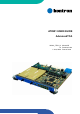


AT8901 Preface
Page vi AT8901 User Guide
List of Tables
1-1 Fabric Interface Options ............................................................................. 1 - 6
1-2 Base Interface Options .............................................................................. 1 - 6
1-3 AT8901 Main Specifications ....................................................................... 1 - 7
1-4 AT8901 Software Specification .................................................................1 - 11
3-1 PCI Slots .................................................................................................... 3 - 3
3-2 Fast Ethernet Management (RJ45) Pin Assignment .................................. 3 - 4
3-3 Fast Ethernet Management (RJ45) LEDs Signification ............................. 3 - 4
3-4 Serial Port (RJ45) Pin Assignment ............................................................ 3 - 5
3-5 Serial console terminal cable interface: RJ45 Female to DB9 Female ..... 3 - 5
3-6 Base Interface Port Mapping ..................................................................... 3 - 6
3-7 Base Uplink (J27) Pin Assignment ............................................................. 3 - 7
3-8 Base Uplink (J27) LEDs Signification ........................................................ 3 - 7
3-9 AMC Bay Address ...................................................................................... 3 - 9
3-10 AMC B1 Channel Assignment ................................................................... 3 - 9
3-11 AMC B2 Channel Assignment ................................................................. 3 - 10
3-12 J30 Pin Assignment ................................................................................. 3 - 13
3-13 J31 Pin Assignment ................................................................................. 3 - 14
3-14 Power Connector (P10) ........................................................................... 3 - 15
3-15 Power Transients ..................................................................................... 3 - 16
3-16 Jumper Settings ( • Default Setting) ......................................................... 3 - 17
3-17 ATCA LEDs Signification ......................................................................... 3 - 19
3-18 Backplane Link LEDs Signification .......................................................... 3 - 20
3-19 Switch LED Assignment ........................................................................... 3 - 21
4-1 POST routines and error codes ................................................................. 4 - 8
4-2 POST Boot Steps ....................................................................................... 4 - 9
4-3 AT8901 sensors ........................................................................................4 - 11
4-4 LED state ................................................................................................. 4 - 15
4-5 OOS LED state ........................................................................................ 4 - 15
4-6 Health LED state ...................................................................................... 4 - 16
4-7 FLASH Partition Scheme (64MB) ............................................................ 4 - 17