
Owner's manual


AT8901 Hardware Description
Page 3 - 20 AT8901 User Guide
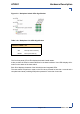
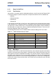
Figure 3-5: Backplane Switch LEDs Signification
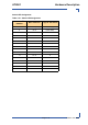
Table 3-18: Backplane Link LEDs Signification
The four front panel ATCA LEDs display the board’s health status.
It also provides 16 LEDs for status indication for the base interfaces. User LED1 displays infor-
mation on the status of the base switch.
Each RJ45 displays the status of the link with the two integrated LEDs.
The reset switch will perform a reset on the CPU when pressed for less than 1 second and a
complete board reset (including IPMI) when pressed for more than 2 seconds.
STAT/ACT LEDs 1-16
OFF Link Down
ON Link Up and no activity
BLINK Link up and activity