
Owner's manual

AT8901 Hardware Description
Page 3 - 7 AT8901 User Guide
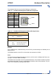
Base Interface Uplink
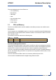
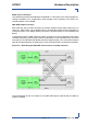
The Hub Board supports four base interface uplinks to the front panel. The switch is connected
to the RJ45 connectors with integrated status LEDs on the front panel via a 10/100/1000BASE-
T quad PHY and two 10/100/1000BASE-T dual magnetics. GbE channels 0/1 to 0/4 of the
switch map to uplink channels 1 to 4.
The upper four RJ45 connectors on the front panel are not used for the AT8901.
Table 3-7: Base Uplink (J27) Pin Assignment
Signal Pin
DB+ 1
DB- 2
DA+ 3
DD+ 4
DD- 5
DA- 6
DC+ 7
DC- 8
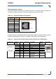
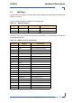
Table 3-8: Base Uplink (J27) LEDs Signification
Speed LED (yellow)
OFF 10BASE-T
BLINK 100BASE-TX
ON 1000BASE-T
Status LED (green)
OFF Link Down
ON Link Up and no activity
BLINK Link Up and activity
Yellow
Green
Yellow
Green
1
8
1
8
1