
Manual


78 AT8050
www.kontron.com
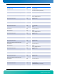
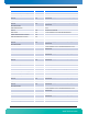
The following table gives AMC clock connectivity details for "Onboard Clock Multiplexer" (On-Carrier Device
1).
Table 4-36:Onboard Clock Multiplexer
Family 0x02 Reserved for PCI Express
Accuracy Level 0x0E Gen 2 Capable PCIe Clock
Frequency 0x05F5E100 As defined in AMC.1 R2.0
Min Clock 0x05F5E100 As defined in AMC.1 R2.0
Max Clock 0x05F5E100 As defined in AMC.1 R2.0
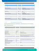
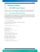
Field Value Description
Record Type ID C0h
Record format version 02h
Record Length *Calculated
Record Checksum *Calculated
Header Checksum *Calculated
Manufacturer ID 00315Ah PICMG Record ID
PICMG Record ID 2D Clock Configuration Record
Record Format Version 00h
Clock Resource Id 0x01
7:6 00b = On-Carrier device 5:4 0h (reserved) 3:0 01h = On-
Carrier Device 1 (Clock Multiplexer)
Clock Configuration Descriptor Count 0x0A
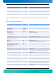
Clock Configuration Descriptors
Clock Id 0x00 Receiver input from CLK1A
Clock Control 0x01 7:1 0h (reserved) [0] 1b = Activated by Application
Indirect Clock Descriptors Count(m) 0x02
Direct Clock Descriptors Count(n) 0x00
Indirect clock Descriptor
Features 0x02
7:2 0h (reserved) [1] 1b = Connected through PLL [0] 0b =
Clock Receiver
Dependent ClockId 6
Features 0x02
7:2 0h (reserved) [1] 1b = Connected through PLL [0] 0b =
Clock Receiver
Dependent ClockId 7
Direct clock Descriptor none
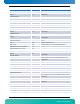
Clock Id 0x01 Receiver input from CLK1B
Clock Control 0x01 7:1 0h (reserved) [0] 1b = Activated by Application
Indirect Clock Descriptors Count(m) 0x02
Direct Clock Descriptors Count(n) 0x00
Indirect clock Descriptor
Features 0x02
7:2 0h (reserved) [1] 1b = Connected through PLL [0] 0b =
Clock Receiver
Field Value Description