
User Manual


18810 Table-Style Keyboard Stand »Omega«
- An appealingly designed practical and very stable keyboard stand
- Load capacity: 80 kg
- Four point support with protective rubber discs
- Support arms width: 180, 300, 420, 550, 670, 790 mm, depth: 345 mm
- Adjustable height from 600 – 1020 mm in 28 stages,
- comfortable and quick with engage and lock knobs
- Weight: 9.5 kg
- Optional add-ons:
- 18813 Add-On for a 2nd Keyboard or Laptop
- 18814 Adapter (for Microphone Holder 18956 / Sheet Music Holder 18958)
- 18815 Side Laptop Holder
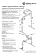
SAFETY NOTES
- Tighten the screw connections 1, 3, 5
- The engage and lock knobs 5 must always be engaged
- The leg frames 6 must always be set at the same height
- The long side of the support arms must be above the long side
- of the table legs
- Ensure the ground is level and suitable for the keyboard stand
- Max. height has been reached when a leg frame has been
- extended to STOP; See the section on HEIGHT ADJUSTMENT
- There is an inherent hazard of pinching when adjusting this
- product. Please take care when assembling and disassembling
- the keyboard stand.
ASSEMBLY INSTRUCTIONS
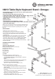
COMPONENTS
1 Carriage bolt M6 x 60 mm (2x)
2 Keyboard support arms (2x)
3 Fixing nuts M6 with washers ø 6.4 mm (2x)
4 U frame with cable ties
5 Engage and lock knobs (2x)
6 Leg frame left
7 Leg frame right
8 Bumpons (4x)
ASSEMBLY
A Assemble leg frames 6, 7 with U frame 4
A - Slot right leg frame 6 (holes on outer side) in the
A- U frame 4. Adjust and fix at the desired height by screwing in
A- the engage and lock knob 5.
A - NOTE:
A- The pin of the engage and lock knob 5 must be submerged in
A- a bore hole of the leg frame 6 before being tightened.
A - Assemble the second leg frame likewise.
A- Take care to adjust to the same height (use scale).
B To fix the support arms 2 to U frame 4.
B - First of all decide at where the support arms are going to be
B - placed and which of the six bore holes you are going to use:
B - a, b, c, d, e or f.
B - Then place a support arm 2 at the required positions on the U
B - U frame 4.
B - Slot a carriage bolt through a support arm 2 and U frame 4
B - and fix using a fixing nut and washer 3.
B - Attach the second support arm in the same way as the first
B - support arm in position a, b, c, d, e or f.
B - If required attach Bumpons 8 at the required places.
Thank you for choosing this product. This instruction manual informs
you about the important steps to set up and handle the product. We
recommend to keep the manual in a separate place for a possible
later use.
KÖNIG & MEYER GmbH & Co. KG
Kiesweg 2, 97877 Wertheim, www.k-m.de
18810-015-55/76/91 Rev.06 03-80-254-00 2/18