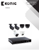
SAS-DVRSET35/45 SAS-DVR1004/1008/1016 SAS-CAM11x0/12x0 MANUAL
ENGLISH Contents SAFETY INSTRUCTION ������������������������������������������������������������������������������������������������������������� 5 CHAPTER 1: FEATURES AND FUNCTIONS ����������������������������������������������������������������������������� 6 CHAPTER 2: OVERVIEW ����������������������������������������������������������������������������������������������������������� 7 2.
ENGLISH 5.2.4.5 Email set �������������������������������������������������������������������������������������������������������������������������������� 27 5.2.4.6 DDNS Set ������������������������������������������������������������������������������������������������������������������������������ 28 5.2.5 Alarm ������������������������������������������������������������������������������������������������������������������������������������������������� 28 5.2.5.
ENGLISH 6.3.3.6 System ����������������������������������������������������������������������������������������������������������������������������������� 47 6.3.3.7 Advanced ����������������������������������������������������������������������������������������������������������������������������� 48 6.3.4 Local setting ������������������������������������������������������������������������������������������������������������������������������������ 50 6.3.
ENGLISH Safety Instruction 1. Read Instruction All the safety and operating instruction should be read before the equipment is operated. 2. Power sources This equipment should be operated only from the type of power source indicated on the marking label. If you are not sure of the type of power, please consult your equipment dealer. 3.
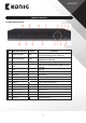
ENGLISH Chapter 1: Features and Functions Function Brief and Description Double video output; with monitor, VGA virtual output port or Real time monitoring HDMI Output; Support net-viewer and MP live surveillance and also support zoom in/out, auto sequence and PIP display. H.
ENGLISH Chapter 2: Overview 2.
ENGLISH 2.
ENGLISH 2.
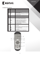
ENGLISH 2.4 Mouse Operation Except using buttons of front panel or remote controller, you also can use mouse to perform system operation. TYPE Click left key of Mouse Click right key of Mouse Double-click Left key of Mouse Moving Mouse Sliding Mouse Function In menu lock mode, enter into pop-up menu and click any sub menu to pop up Log-in window; on menu unlock mode, enter into pop-up menu, and then click left key to enter into any sub menu directly.
ENGLISH Chapter 3: DVR CONNECTION 3.1 HDD Installation Caution: Please do not Install or take out hard drive when DVR is running! HDD Installation: (1) Cut power firstly, and then remove screws and open DVR upper cover carefully; (2) Insert Power Cord and data cable into Pin of hard drive securely; (3) Remove the screws on the HDD bracket; fix the HDD to the bracket and then fix the bracket with HDD to DVR body; (4) Put the upper cover back carefully, re-attach screws.
ENGLISH 4.2 Live Interface Picture 4-2 After finishing initialization the system will enter into screen. Picture 4-2 is the 16-split display defaulted by system, which is showing no video input status. Once there are video inputs, the screen will display live images from the cameras.
ENGLISH 5.
ENGLISH 5.2 Main Menu On mode, click [Menu] button on the front panel or Remote controller to enter into Main menu interface shown as Picture 5-2. And also you can click [ ] icon to enter the main menu screen. In Main Menu mode, you can control device management settings, such as Display, Record, Network, Search, Device, System and Advanced setting etc. Picture 5-2 5.2.1 Display 5.2.1.
ENGLISH 5.2.1.2 Output mode Go to [Main menuDisplayOutput] to enter into the output set interface shown as Picture 5-5. Click [Live] to pop up the interface shown as Go to [Main menuDisplayOutput] to enter into the output set interface shown as Picture 5-6. Now you could perform channel sequence setting. Picture 5-5. Picture 5-5 Click [Spot output] option and set relative parameters shown as Picture 5-7. Picture 5-6 Click [Spot sequence] to enter into the interface shown as Picture 5-8.
ENGLISH ¾¾ Transparency: allow you adjust menu’s transparency, and its range is 1~128. ¾¾ Margin: allow you adjust the whole screen’s margin. Details operations please refer to the Picture 5-10. Volume: allow you adjust the DVR volume shown as Picture 5-11. Picture 5-10 Picture 5-11 5.2.1.3 Privacy Zone The function Allow you setup privacy zone parameters according to Picture 5-12. Each channel could set up to four privacy zones, and please follow below steps to set: 1.
ENGLISH 5.2.2 Record set 5.2.2.1 Record parameters Picture 5-14 Click [Main menuRecordRecord Para] to enter into the interface shown as Picture 5-14. ¾¾ Channel: allow you setup the channel you desired. ¾¾ Record: allows you set up record status (Enable/ Disable) of each channel ¾¾ Pack Duration: indicates maximum continuous record time (15, 30, 45 and 60 min). ¾¾ Pre-record: Motion detection and I/O triggered record support Pre-record function. 5.2.2.
ENGLISH 5.2.2.3 Main Stream Go to [Main menuRecordMain Stream] to enter into the interface shown as Picture 5-16. ¾¾ Resolution: support 960H and D1. 960H: includes WD1, WHD1 and WCIF; D1: include D1, HD1 and CIF ¾¾ Frame rate: PAL: 1-25 f/s; NTSC: 1-30 f/s. ¾¾ Bit rate: user could select the relative value by pull-down menu. ¾¾ Audio: When tick-selecting the option, system will record video stream with audio simultaneously.
ENGLISH ¾¾ Time Search: In the , user can search for a specific date and time for a recording and view it in Playback mode. This is useful for hunting a specific recording of an incident if you know the date and time it occurred. ¾¾ File List: click [File List] button to enter into the [Event Search] screen shown as Picture 5-19, the video records for the time quantum will appear in the screen.
ENGLISH 5.2.3.3 Time Axis setup, file clip and zoom in/out 1) The DVR supports the processing control bar function when playing back record files shown as Picture 5-19A (Up to 4CH is available). 2) Click [ ] icon beside the processing bar to pop up the interface shown as Picture 5-19A-1. Picture 5-19A-1 Picture 5-19A Time Axis: defaulted to 24hours, and allow user select 2hours, 1hour, 30minutes or user-defined.
ENGLISH • Record Clip and backup function and Zoom in/out function Picture 5-19C Picture 5-19B-2 ¾¾ Clip and backup: When one channel is playing-back, the [ ] icon will appear in the [Play control] bar shown as Picture 5-19B-1. Click the icon to start video clip function, click it again to end the function and pop up the dialog shown as Picture 5-19B-2. Now, allow you select if you will save the clipped video file.
ENGLISH 5.2.3.5.1 back-up file based on event In the [File List] mode, if you wish to backup records, please tick-select the BAK check-boxes which correspond to the records and click [Backup] button to enter into the below windows illustrated in Picture 5-21.
ENGLISH Picture 5-26 Picture 5-25 Play button: click the icon to playback the backup record Pause button: click the icon to pause the backup record Stop button: click the icon to stop the backup record Next: Click the icon to play next record Prev.
ENGLISH 5.2.3.6 Log Search Go to [Main menuSearchLog] option to enter into the Log search interface shown as Picture 5-28. Herein allow you preview the log information you have searched. And click [Backup] to export all the log information which is listed. For other button functions please refer to previous section 5.2.3.4-Event Search. Picture 5-29 Picture 5-28 5.2.4 Network 5.2.4.1 Network set Click [Main menuNetworkNetwork] to enter into the below interface shown as Picture 5-30.
ENGLISH 5. Visit a remote DVR http: // public net IP: HTTP port (such as: 19010) http: //intranet IP: HTTP port (such as: 19010 - only use for Intranet) 6. Input the IP address of your domain name server Friendly Reminder: 1. All the parameters you set are available only when you click [Apply] and after system are restarted. 2. User needs to change MAC address when there are multiple DVRs at the same local area network. Details please refer to section 5.2.7.3 Information.
ENGLISH When selecting 3G from the Type. Details please follow below steps: 1. Input Mobile Port (China Telecom:#777;Others: *99#) 2. Click . System will automatically capture IP. 3. Enter IP address:web port to visit DVR remotely. Picture 5-34 Under the above four net mode, you can visit your remote DVR via DDNS and apply for free DDNS account from the websites: www.3322.org or www.dyndns.org. 5.2.4.
ENGLISH Friendly Reminder: The router’s port forwarding interface may be different, however, when entering into virtual server, user will always need forward port (range: 1025~65535) of router to IP address of DVR allocated or automatically captured, and select [All] or [Both] in corresponding protocol column and save the above setting. Above steps may differ from the router device depending on the manufacturer. Picture 5-35 5.2.4.
ENGLISH Picture 5-38 ¾¾ Sender address: indicates sender’s email address. The email address should be consistent with the server you use. That is to say, when you use email address – aaa@gmail.com, the according server should be smtp.gmail.com. ¾¾ Receiver address: indicates receiver’s email address. The email address is used to receive image transmitted from DVR alarm. Please clear the images you have received as soon as possible to avoid overloading your email account. 5.2.4.
ENGLISH ¾¾ Buzzer time: you can set how long the buzzer will sound when motion is detected (off, 10s, 30s, 40s, 60s). ¾¾ Send Email: Allows you set the alarm images is issued to a specified email. ¾¾ Full screen Alarm: The function is defaulted to “On”. When the motion is detected, the corresponding channel will be switched to the full screen mode. ¾¾ Record Channel: the record channel will be activated when the object move is detected.
ENGLISH ¾¾ Record Channel: allow you select channels you want to record. ¾¾ Post Recording: you can set how long alarm record will last when alarm ends (30s, 1minute, 2minutes, 5minutes). ¾¾ Copy: allow you copy all the setting of one channel to other ones. Alarm Type Video Loss Motion Detection I/O Status HDD loss Function Sends alarm when DVR can’t receive video signal (such as camera damage, cable broken or damaged or power supply malfunction).
ENGLISH ¾¾ Auto-overwrite: When set to ENABLE the DVR will record over the oldest files on the hard drive. The DVR will always be able to record events as they happen, however, it does means that you’ll need to get important events off the HDD before they’re overwritten; and if overwrite is set to DISABLE the DVR will stop record once the DVR is full. Whilst you won’t lose old footage, you run the risk of missing new events as they happen. Be sure you want to do this before selecting it.
ENGLISH 5.2.7 System 5.2.7.1 General Click [Main MenuSystemGeneral] to enter into the interface shown as Picture 5-49 You will be allowed to modify system date/time, date/time format, time zone, language, video format and menu time out. And click [DST Setup] button to enter into the below interface shown as Picture 5-50, and you are allow to configure DST status and mode. ¾¾ Click [NTP setup] to enter into the interface shown as Picture 5-51 and now allow you enable/ disable the NTP function.
ENGLISH The model supports up to seven users with one Admin and six users. Click [Edit] button to enter into the [User Edit] interface shown as Picture 5-53. And input user name and password. Select one and click , and then enter into interface shown as Picture 5-54. [Admin] is authorized to set common user’s authority. ¾¾ Log Search: allow you check all the system logs. ¾¾ Parameter: allow you set all the parameters.
ENGLISH ¾¾ Auto Reboot: You can enable the auto maintain function regularly as per user’s need. ¾¾ System Upgrade: After decompressing update file package, copy the file named “dvrupgrade” to root directory of U flash disk; Insert the U flash disk into USB port of DVR; Click . Picture 5-56 ¾¾ Load Default: If [Load Default] is selected, you can initialize the system to the ex-factory default. ¾¾ Reboot: Click [Reboot] button to manually restart DVR system.
ENGLISH Friendly Reminder: Administrator has full authority over Main Menu operations and has an authority to limit common user’s operation. Picture 5-59 5.4 Split mode The model displays 4/8 live images in the sequence of single, 4-split and 9-split modes. If you enter into 4-split mode, the live images will be displayed in turn CH1~4, CH5~8… and CH13~16. If you enter into 9-split mode, the live images will be displayed in turn CH1~9CH10~16. 5.
ENGLISH 5.6 PIP Mode You can display a Picture-in-Picture in live mode. PIP has two display modes, including 1x1 display mode and 1x2 display mode. 1x1 display mode 1x2 display mode 5.7 Record Search You could enter into [Record Search] menu from Pop-up menu conveniently and quickly and search/playback the record histories. We introduced Record search details previously in section 5.2.3.1. 5.
ENGLISH Chapter 6: Web Application Manager 6.1 ActiveX control download and installation Open your web browser and input the IP address and web port of DVR, such as: http://172.18.6.202:8080/. If your computer is connected to internet, it will download and install “ActiveX” Plug-in automatically. If your computer system is Vista, you may need to setup the user authority. Details please refer to the below picture: Start→Setup→Control panel (Tick “√” use UAC to help protect your computer and confirm OK).
ENGLISH If running the web application for the first time, you need about one minute to finish download and install the ActiveX controls, please wait patiently. Note: If you want to use the undated webcam at one computer which you already login before, please delete the old IE webcam and click [StartRun] and then input the command characters: “regsvr32/u HiDvrOcx.ocx”, then login again. Picture 6-1 6.
ENGLISH 6.3 Live interface After successful logging-in web manager, you will enter into the Live interface shown as Picture 6-3 Picture 6-3 6.3.1 Menu Bar Menu bar include [Live], [Replay], [Configuration], [Path Configuration] and [Logout] options 6.3.1.1 Live Display After running the Web Application Manager on your local PC, system will be defaulted to enter into interface shown as Picture 6-3.
ENGLISH 6.3.1.2 PTZ Control ① PTZ moving Direction control: allow you control PTZ camera’s direction. And the middle button is called [Auto-cruise] button. : PTZ speed control bar ② ③ : Iris, Focus and Zoom control ④ : Preset setting/clear; Start cruise/stop cruise Picture 6-5 6.3.1.3 Video control : Adjust video Hue : Adjust video brightness : Adjust video Contrast : Adjust video saturation : Recover ex-factory default value Picture 6-6 6.3.
ENGLISH 6.3.2.1 Record search Firstly, select one day you want to check and tick-select and the channels you desire to playback shown as Picture 6-8. Picture 6-8 Secondly, select record type (Normal record, Alarm record and All) and then click < > button shown as Picture 6-9. On the time axis, red part stand for alarm record, yellow stand for normal record and original part stand for no record during this period.
ENGLISH Detail brief description is shown as below list Key Description Play Key Description Open/close audio Pause Volume adjust Stop By frame Playback control bar (x1/2,1/4,1/8, normal, x2, x4, x8) Stop all the play Clip Single channel mode Snapshot Quad mode Download Full screen Open all the channels Toggle between original proportions and Adaptive Screen Resolution.
ENGLISH Record file download Click [ ] icon to enter into the below interface shown as Picture 6-12. Picture 6-12 Tick-select the record file you want to download and click [Start download]. System will download the record file in turn and save to local PC. 6.3.3 Configuration 6.3.3.1 Display Configuration Unfold [Display] option to find its sub-options: Live and Privacy zone 1. Live: Allow you modify channel name, Position, Show time and Record time.
ENGLISH 6.3.3.2 Record Click option to unfold its sub-options: Record parameter, Schedule and Main stream. Picture 6-15 Picture 6-17 Picture 6-16 1. Record Parameters: Under [Record parameters] option, allow you set channel, record enable, pack time and Pre-record status shown as Picture 6-15; 2. Schedule: Detailed parameters please refer to DVR local setting (shown as Picture 6-16). Green stand for Normal record; Yellow stands for Motion detection; Red stands for I/O triggered record. 3.
ENGLISH Picture 6-19 Picture 6-20 2. Sub stream (shown as Picture 6-21): Relative parameters should be consistent with DVR local setting. Picture 6-21 3. Email setting: Click [Email setting] option to allow you set alarm email configuration parameters shown as Picture 6-22. Detailed parameters should be consistent with DVR local setting. 4.
ENGLISH 6.3.3.4 Alarm Set Click option to unfold its sub-options: Motion, I/O Alarm shown as Picture 6-24. Picture 6-24 1. Motion Detection: allow you configure its , , and etc.. Details setting should be consistent with DVR local setting (Shown as Picture 6-25). Picture 6-25 2. I/O Alarm: allow you configure , , and etc..
ENGLISH 6.3.3.5 Device Click to unfold its sub-options: HDD and PTZ. 1. HDD: Allow you check out HDD status and overwritten time shown as Picture 6-27. Detail setting should be consistent with DVR local setting. Picture 6-27 2. PTZ: Configuration (shown as Picture 6-28): Details setting should be consistent with DVR local setting. Picture 6-28 6.3.3.6 System Click option to unfold its sub-options: General, Users and information. 1.
ENGLISH 2. Users: Allow you configure user name and password shown as Picture 6-30. Details setting should be consistent with DVR local setting. Picture 6-30 3. Information: Allow you check out device name, number, type, MAC address, software version, IE version and hardware version shown as Picture 6-31. Picture 6-31 6.3.3.7 Advanced 1. Click to unfold its sub-options: System update, Load default, Events and system maintain etc..
ENGLISH Please follow below steps to upgrade the system: a. Select the upgrade file’s path shown as Picture 6-33. Please note that the format of upgrade file is *.sw. Picture 6-33 b. Click , now processing bar will display current upgrade status shown as Picture 6-34. Picture 6-34 2. Load Default: allow you recover defaulted parameters of DVR remotely shown as Picture 6-35. Details setting should be consistent with DVR local setting.
ENGLISH 3. Events: Allow you configure abnormal type, buzzer output time, and alarm email and show message shown as Picture 6-36. Details setting should be consistent with DVR local setting. Picture 6-36 4. Maintain: Allow you set auto system maintain for DVR remotely shown as Picture 6-37. Detail setting should be consistent with DVR local setting. Picture 6-37 6.3.
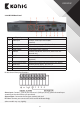
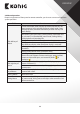
ENGLISH Chapter 7: Appendix 7.1 Operation Function Table Type Title Time setting Language select Channel setting Basic setting Advanced Setting Network setting Description Set system date/time, display format and day-light saving time. Set system language. Set CH title and position; adjust image color parameter value; set CH display to ON/Off and time display/recording time overlaying to On/Off. Record Set image quality, resolution, volume, record mode an pack setting time.
ENGLISH Type Network Function Title Live display Remote record Remote playback PTZ control Auxiliary function parameter set of DVR remotely Network download System info () Menu button Enter Default Recovery ESC Time setting HDD Manage Net setting Basic application Guide System Info Mobile Monitoring Other Description Rea-time video surveillance remotely. Set record mode and status of DVR remotely. Check local record history via network.
ENGLISH 7.2 Record Alarm setting Under the record mode, [ ] icon or [ ] icon will appear on the screen, and alarm will be issued. You have configured record type to on the mode, once one alarm occurred, the record will be saved as Normal record, on the contrary, configured to , once one alarm occurred, the record saved as Alarm record. Under the Scheduled mode, no-record interval allow you actiate manual record and the record file can be saved as Normal record. 7.
ENGLISH 7.4 Troubleshooting 1. Q: What can I do if the system does not detect the HDD? A: Check if the power supply system is properly connected and data cord and power cables are securely connected. 2. Q: We have changed the password but do not remember the new password, how can we access the system? A: If you forget system password, please consult with the service personnel. 3.
ENGLISH 7.6 System Connection Diagram Connection cable To camera input DVR To DC 12 V input Max.
ENGLISH Chapter 8: Cameras SAS-CAM1100/1110, 1200/1210 Specifications: • Image chip: 1/4” CMOS • Lens: 3.60 mm • Horizontal resolution: 700 TVL • View angle: 45° • Infrared LED: 24 pcs, 5~10 M • Light sensitivity: 1.5 lux • Electronic shutter: 1/50(1/60)~1/100,000 sec. • S/N ratio: > 48 dB • Gain: auto • Gamma correction: > 0.45 • Protection: IP66 • Working temperature: -20 °C~55 °C • Video out: 1.
ENGLISH • Light sensitivity: 1.5 lux • Electronic shutter: 1/50(1/60)~1/100,000 sec. • S/N ratio: > 48 dB • Gain: auto • Gamma correction: > 0.45 • Protection: IP66 • Working temperature: -20 °C~55 °C • Video out: 1.0 V p-p/75 Ω • Voltage: DC 12 V • Dimensions: 100x75 mm • Weight (with bracket): 250 g Product description: 1. Camera lens 2. IR LED for night vision 3. Light intensity sensor 4. BNC connector for video 5.
ENGLISH Chapter 10: General information Warranty: Any changes and/or modifications to the product will void the warranty. We cannot accept any liability for damage caused by incorrect use of this product. Disclaimer: Designs and specifications are subject to change without notice. All logos, brands and product names are trademarks or registered trademarks of their respective holders and are hereby recognized as such.