
Universal Remote User Manual

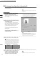
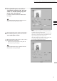
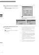
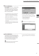
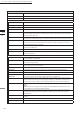
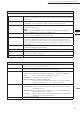
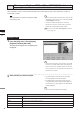
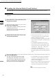
Table Of Contents
- Safety Symbols
- Notes on this Manual
- Trademarks
- About This Manual and Related Documents
- Safety Precautions
- Software Restrictions
- Notes On Use
- Notes On Storage
- Contents
- Conventions for Command Reference (Chapter 2)
- Chapter 1 Forward
- Chapter 2 Command Reference
- File Menu
- File – New
- File – Open
- File – Save – Elements
- File – Save – Scene
- File – Save as – Elements
- File – Save as – Scene
- File – Import – Elements
- File – Import – Digitizer – One Scan
- File – Import – Digitizer – Step Scan
- File – Import – Digitizer – One Scan
- File – Import – Digitizer – Step Scan
- File – Import – Digitizer – PC Card
- File – Import – Digitizer – PC Card
- File – Import – Digitizer – One Scan
- File – Import – Digitizer – Step Scan
- File – Import – Digitizer – PC Card
- File – Import – Digitizer – One Scan
- File – Import – Digitizer – Step Scan
- File – Import – Digitizer – Easy Align
- File – Import – Digitizer – PSC-1
- File – Export – Elements
- File – Export – Images
- File – Remove Elements
- File – Preferences
- File – Select Digitizer
- File – Exit
- View Menu
- Select Menu
- Edit Menu
- Build Menu
- Build – Registration – Initial – Manual
- Build – Registration – Initial – Auto
- Build – Registration – Fine – Elements
- Build – Registration – Fine – Points
- Build – Move – Points
- Build – Move – Elements
- Build – Move – To Origin
- Build – Move – To X-Y-Z
- Build – Rotate – Elements
- Build – Merge
- Build – Fill Holes – Manual
- Build – Fill Holes – Auto
- Build – Smooth – Element
- Build – Smooth – Points
- Build – Subsample – Uniformly – Element
- Build – Subsample – Uniformly – Points
- Build – Subsample – Adaptively – Element
- Build – Subsample – Adaptively – Points
- Build – Modify – Element
- Build – Modify – Points
- Build – Subdivision – Element
- Build – Subdivision – Points
- Build – Triangulate – Elements
- Build – Triangulate – Polygons
- Build – Texture Blending
- Build – Check Polygons – Element
- Build – Check Polygons – Polygons
- Info Menu
- Window Menu
- Tool Menu
- Pop-up Menus in Element View Window
- View Mode – Front/Right/Left/Back/Top/Bottom/Isometric/Perspective
- Rendering Mode – Wireframe/Shading/Texture Mapping/Wireframe+ Shading/Wireframe + Texture Mapping
- Show Vertex/Hide Vertex
- Show Normal/Hide Normal
- Show Axis/Hide Axis
- Smooth Shading/Flat Shading
- Select element from window
- Create clone window
- Close window
- Property
- Pop-up Menus in Element List
- Pop-up Menus in Image Window
- File Menu
- Chapter 3 Appendix
90
Chapter
2
File
Menu
900
910
File – Import – Digitizer – Step Scan (When VIVID 900/910 is Selected)
n Performing Scan Operations Automatically
If the bench top frame set is used and calibration chart data exists, a series of scan operations can be pro-
cessed automatically.
1
From the [File] menu, select [Import],
[Digitizer] and then [Step Scan].
The [File-Import-Digitizer-Step Scan] dialog
box will appear.
2
Select the desired installation direction
of the VIVID digitizer.
From the [Hardware] tab, check the [Bench
Top Frame set] checkbox, and select the VIVID
digitizer installation direction by clicking the
corresponding [Mounted] radio button.
Check the [Auto Scan] checkbox under the
[Hardware] tab.
Select [Vertical] if the VIVID digitizer is
mounted vertically, or select [Horizontal] if it is
mounted horizontally.
• The monochrome monitor image currently cap-
tured by the VIVID 910 or VIVID 900 will ap-
pear in the image area of the dialog box.
M
emo
If the VIVID digitizer is mounted horizontally, the pre-
view image will be in portrait form.
After the image is converted to 3D, it will be displayed ac-
cording to the coordinate system of the VIVID.
M
emo
For details of how to save the calibration chart data, refer
to page 87,88.
Operating Procedure
3
Place the object on the rotating stage.
Note
IftheVIVIDdigitizerismountedontheframesethori-
zontally,theobjectwillbeaffectedbyrepeatedreection
ontherotatingstagesurface,preventingcorrectscan
operation.Topreventthis,placeanappropriateitemof
thefollowingthicknessundertheobjecttoraiseit.
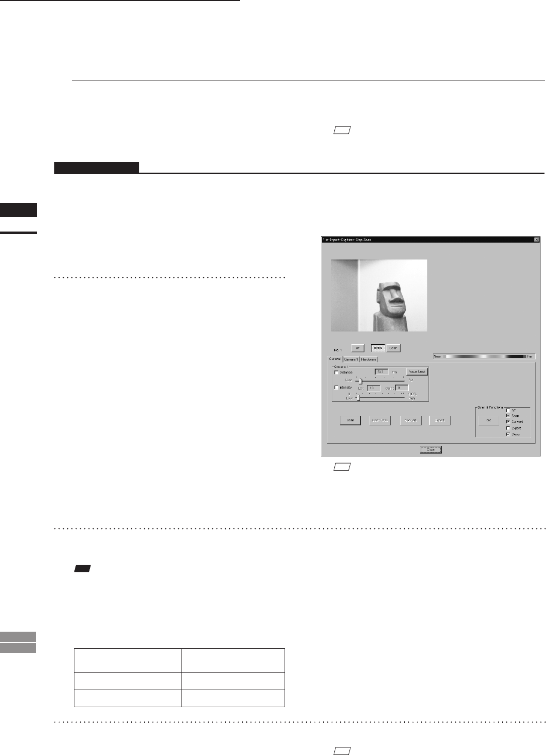
Measurement
Distance
Thickness of Item
600 mm Approx. 30 mm
1000 mm Approx. 20 mm
4
To display the object in the middle of the
image area, change the position of the
object or move the rotating stage back
and forth to change the view angle.
M
emo
If necessary, replace the lens attached to the VIVID
digitizer.