
Universal Remote User Manual
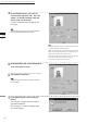
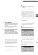
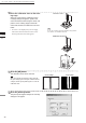
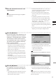
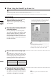
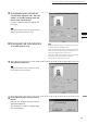
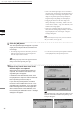
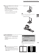
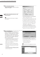
Table Of Contents
- Safety Symbols
- Notes on this Manual
- Trademarks
- About This Manual and Related Documents
- Safety Precautions
- Software Restrictions
- Notes On Use
- Notes On Storage
- Contents
- Conventions for Command Reference (Chapter 2)
- Chapter 1 Forward
- Chapter 2 Command Reference
- File Menu
- File – New
- File – Open
- File – Save – Elements
- File – Save – Scene
- File – Save as – Elements
- File – Save as – Scene
- File – Import – Elements
- File – Import – Digitizer – One Scan
- File – Import – Digitizer – Step Scan
- File – Import – Digitizer – One Scan
- File – Import – Digitizer – Step Scan
- File – Import – Digitizer – PC Card
- File – Import – Digitizer – PC Card
- File – Import – Digitizer – One Scan
- File – Import – Digitizer – Step Scan
- File – Import – Digitizer – PC Card
- File – Import – Digitizer – One Scan
- File – Import – Digitizer – Step Scan
- File – Import – Digitizer – Easy Align
- File – Import – Digitizer – PSC-1
- File – Export – Elements
- File – Export – Images
- File – Remove Elements
- File – Preferences
- File – Select Digitizer
- File – Exit
- View Menu
- Select Menu
- Edit Menu
- Build Menu
- Build – Registration – Initial – Manual
- Build – Registration – Initial – Auto
- Build – Registration – Fine – Elements
- Build – Registration – Fine – Points
- Build – Move – Points
- Build – Move – Elements
- Build – Move – To Origin
- Build – Move – To X-Y-Z
- Build – Rotate – Elements
- Build – Merge
- Build – Fill Holes – Manual
- Build – Fill Holes – Auto
- Build – Smooth – Element
- Build – Smooth – Points
- Build – Subsample – Uniformly – Element
- Build – Subsample – Uniformly – Points
- Build – Subsample – Adaptively – Element
- Build – Subsample – Adaptively – Points
- Build – Modify – Element
- Build – Modify – Points
- Build – Subdivision – Element
- Build – Subdivision – Points
- Build – Triangulate – Elements
- Build – Triangulate – Polygons
- Build – Texture Blending
- Build – Check Polygons – Element
- Build – Check Polygons – Polygons
- Info Menu
- Window Menu
- Tool Menu
- Pop-up Menus in Element View Window
- View Mode – Front/Right/Left/Back/Top/Bottom/Isometric/Perspective
- Rendering Mode – Wireframe/Shading/Texture Mapping/Wireframe+ Shading/Wireframe + Texture Mapping
- Show Vertex/Hide Vertex
- Show Normal/Hide Normal
- Show Axis/Hide Axis
- Smooth Shading/Flat Shading
- Select element from window
- Create clone window
- Close window
- Property
- Pop-up Menus in Element List
- Pop-up Menus in Image Window
- File Menu
- Chapter 3 Appendix
86
Chapter
2
File
Menu
900
910
File – Import – Digitizer – Step Scan (When VIVID 900/910 is Selected)
• If the color and range images are not scanned at
the same time, clicking the [Color Read] button or
double-clicking on the image will capture a color
image in the [General] tab in the [File-Import-
Digitizer-Step Scan] dialog box and display it.
• Dragging the mouse on the color image will
enlarge the image. If necessary, enable color cor-
rection such as “Dark”, “Log” and “Smooth”, and
load the color image again.
• If the type of rotating stage has not been desig-
nated, turn the rotating stage manually to the next
angle displayed in the “Next angle: **degree”
message dialog box.
M
emo
Step 8 and subsequent steps can be processed automati-
cally. (For details, refer to page 90.)
9
Click the [OK] button.
The next specied angle will appear in [Current
angle], and the object will be scanned for the
next image.
• If a rotating stage has been selected by the Turn-
table, the stage will turn to the next angle and
then the object will be scanned.
• To cancel scan, click the [Cancel] button instead
of the [OK] button, and repeat steps 6 to 8.
Note
Therotatingstagemayrotateintheoppositedirection
duringmeasurementdependingonitstype.
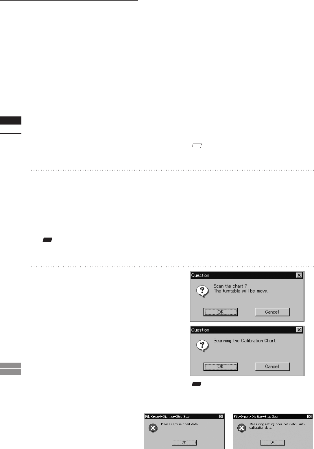
10
Repeat step 9 until shots from all the
desired angles are captured.
When shots from all the desired angles are
captured, the “Read the chart data ?” mes-
sage dialog box will appear.
If calibration chart data already exists, click
the [OK] button to import it. After the data has
been imported, proceed to step 13.
If you click the [Cancel] button, the CScan
the chart? The turntable will be move.” mes-
sage dialog box will appear. If you click [OK]
button the stage will move to the angle that
allows measurement of the calibration, and
the “Scanning the Calibration Chart.” message
dialog box will appear.
Note
Ifnochartdataexistsortheexistingchartdatadoesnot
matchthemeasurementconditions,thefollowingerror
messageswillappear.