
Universal Remote User Manual
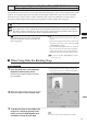
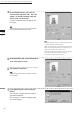
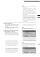
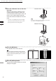
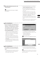
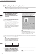
Table Of Contents
- Safety Symbols
- Notes on this Manual
- Trademarks
- About This Manual and Related Documents
- Safety Precautions
- Software Restrictions
- Notes On Use
- Notes On Storage
- Contents
- Conventions for Command Reference (Chapter 2)
- Chapter 1 Forward
- Chapter 2 Command Reference
- File Menu
- File – New
- File – Open
- File – Save – Elements
- File – Save – Scene
- File – Save as – Elements
- File – Save as – Scene
- File – Import – Elements
- File – Import – Digitizer – One Scan
- File – Import – Digitizer – Step Scan
- File – Import – Digitizer – One Scan
- File – Import – Digitizer – Step Scan
- File – Import – Digitizer – PC Card
- File – Import – Digitizer – PC Card
- File – Import – Digitizer – One Scan
- File – Import – Digitizer – Step Scan
- File – Import – Digitizer – PC Card
- File – Import – Digitizer – One Scan
- File – Import – Digitizer – Step Scan
- File – Import – Digitizer – Easy Align
- File – Import – Digitizer – PSC-1
- File – Export – Elements
- File – Export – Images
- File – Remove Elements
- File – Preferences
- File – Select Digitizer
- File – Exit
- View Menu
- Select Menu
- Edit Menu
- Build Menu
- Build – Registration – Initial – Manual
- Build – Registration – Initial – Auto
- Build – Registration – Fine – Elements
- Build – Registration – Fine – Points
- Build – Move – Points
- Build – Move – Elements
- Build – Move – To Origin
- Build – Move – To X-Y-Z
- Build – Rotate – Elements
- Build – Merge
- Build – Fill Holes – Manual
- Build – Fill Holes – Auto
- Build – Smooth – Element
- Build – Smooth – Points
- Build – Subsample – Uniformly – Element
- Build – Subsample – Uniformly – Points
- Build – Subsample – Adaptively – Element
- Build – Subsample – Adaptively – Points
- Build – Modify – Element
- Build – Modify – Points
- Build – Subdivision – Element
- Build – Subdivision – Points
- Build – Triangulate – Elements
- Build – Triangulate – Polygons
- Build – Texture Blending
- Build – Check Polygons – Element
- Build – Check Polygons – Polygons
- Info Menu
- Window Menu
- Tool Menu
- Pop-up Menus in Element View Window
- View Mode – Front/Right/Left/Back/Top/Bottom/Isometric/Perspective
- Rendering Mode – Wireframe/Shading/Texture Mapping/Wireframe+ Shading/Wireframe + Texture Mapping
- Show Vertex/Hide Vertex
- Show Normal/Hide Normal
- Show Axis/Hide Axis
- Smooth Shading/Flat Shading
- Select element from window
- Create clone window
- Close window
- Property
- Pop-up Menus in Element List
- Pop-up Menus in Image Window
- File Menu
- Chapter 3 Appendix
84
Chapter
2
File
Menu
900
910
File – Import – Digitizer – Step Scan (When VIVID 900/910 is Selected)
n When Using the Bench Top Frame Set
M
emo
The VIVID 910 or VIVID 900 can be mounted on the bench top frame set vertically or horizontally.
For the mounting method, refer to the instruction manual of the frame set.
Saving the calibration chart data helps you reduce work time when scanning different objects under the same conditions.
Operating Procedure
1
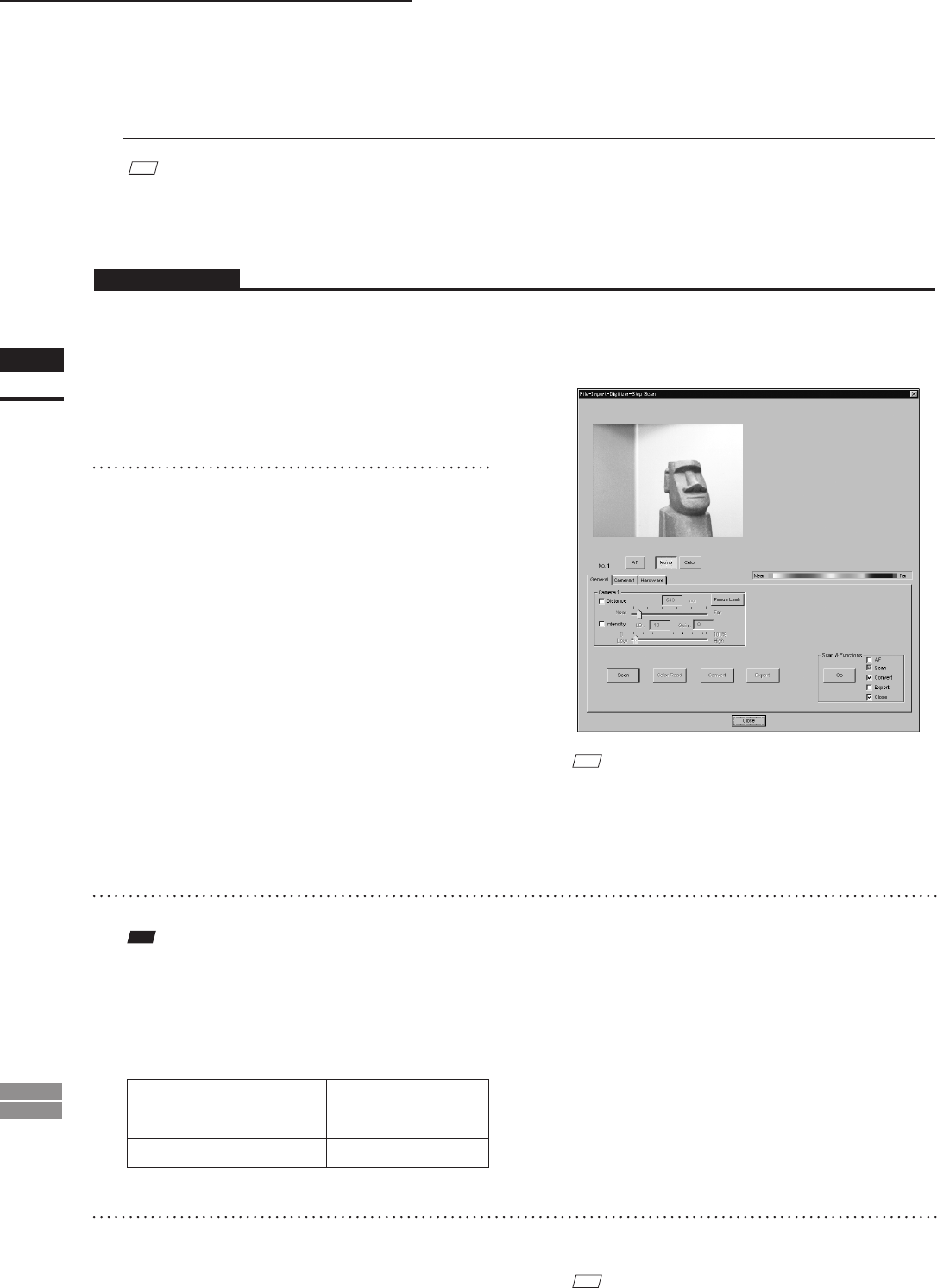
From the [File] menu, select [Import],
[Digitizer] and then [Step Scan].
The [File-Import-Digitizer-Step Scan] dialog
box will appear.
• The monochrome monitor image currently cap-
tured by the VIVID 910 or VIVID 900 will ap-
pear in the image area of the dialog box.
3
Place the object on the rotating stage.
Note
IftheVIVIDdigitizerismountedontheframesethori-
zontally,theobjectwillbeaffectedbyrepeatedreection
ontherotatingstagesurface,preventingcorrectscan
operation.Topreventthis,placeanappropriateitemof
thefollowingthicknessundertheobjecttoraiseit.
Measurement Distance Thickness of Item
600 mm Approx. 30 mm
1000 mm Approx. 20 mm
4
To display the object in the middle of
the image area, change the position of
the object or move the instrument back
and forth to change the view angle.
M
emo
If necessary, replace the lens attached to the VIVID
digitizer.
2
Select the desired installation direction
of the VIVID digitizer.
From the [Hardware] tab, check the [Bench
Top Frame set] checkbox, and select the VIVID
digitizer installation direction by clicking the
corresponding [Mounted] radio button.
Select [Vertical] if the VIVID 910 or VIVID 900 is
mounted vertically, or select [Horizontal] if it is
mounted horizontally.
M
emo
If the VIVID digitizer is mounted horizontally, the pre-
view image will be in portrait form.
After the image is converted to 3D, it will be displayed
according to the coordinate system of the VIVID.