
Universal Remote User Manual
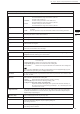
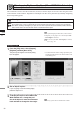
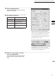
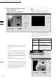
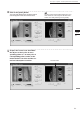
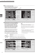
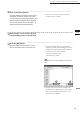
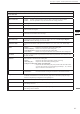
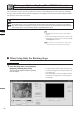
Table Of Contents
- Safety Symbols
- Notes on this Manual
- Trademarks
- About This Manual and Related Documents
- Safety Precautions
- Software Restrictions
- Notes On Use
- Notes On Storage
- Contents
- Conventions for Command Reference (Chapter 2)
- Chapter 1 Forward
- Chapter 2 Command Reference
- File Menu
- File – New
- File – Open
- File – Save – Elements
- File – Save – Scene
- File – Save as – Elements
- File – Save as – Scene
- File – Import – Elements
- File – Import – Digitizer – One Scan
- File – Import – Digitizer – Step Scan
- File – Import – Digitizer – One Scan
- File – Import – Digitizer – Step Scan
- File – Import – Digitizer – PC Card
- File – Import – Digitizer – PC Card
- File – Import – Digitizer – One Scan
- File – Import – Digitizer – Step Scan
- File – Import – Digitizer – PC Card
- File – Import – Digitizer – One Scan
- File – Import – Digitizer – Step Scan
- File – Import – Digitizer – Easy Align
- File – Import – Digitizer – PSC-1
- File – Export – Elements
- File – Export – Images
- File – Remove Elements
- File – Preferences
- File – Select Digitizer
- File – Exit
- View Menu
- Select Menu
- Edit Menu
- Build Menu
- Build – Registration – Initial – Manual
- Build – Registration – Initial – Auto
- Build – Registration – Fine – Elements
- Build – Registration – Fine – Points
- Build – Move – Points
- Build – Move – Elements
- Build – Move – To Origin
- Build – Move – To X-Y-Z
- Build – Rotate – Elements
- Build – Merge
- Build – Fill Holes – Manual
- Build – Fill Holes – Auto
- Build – Smooth – Element
- Build – Smooth – Points
- Build – Subsample – Uniformly – Element
- Build – Subsample – Uniformly – Points
- Build – Subsample – Adaptively – Element
- Build – Subsample – Adaptively – Points
- Build – Modify – Element
- Build – Modify – Points
- Build – Subdivision – Element
- Build – Subdivision – Points
- Build – Triangulate – Elements
- Build – Triangulate – Polygons
- Build – Texture Blending
- Build – Check Polygons – Element
- Build – Check Polygons – Polygons
- Info Menu
- Window Menu
- Tool Menu
- Pop-up Menus in Element View Window
- View Mode – Front/Right/Left/Back/Top/Bottom/Isometric/Perspective
- Rendering Mode – Wireframe/Shading/Texture Mapping/Wireframe+ Shading/Wireframe + Texture Mapping
- Show Vertex/Hide Vertex
- Show Normal/Hide Normal
- Show Axis/Hide Axis
- Smooth Shading/Flat Shading
- Select element from window
- Create clone window
- Close window
- Property
- Pop-up Menus in Element List
- Pop-up Menus in Image Window
- File Menu
- Chapter 3 Appendix
54
Chapter
2
File
Menu
910
File – Import – Digitizer – One Scan (When VIVID 910 is Selected)
11
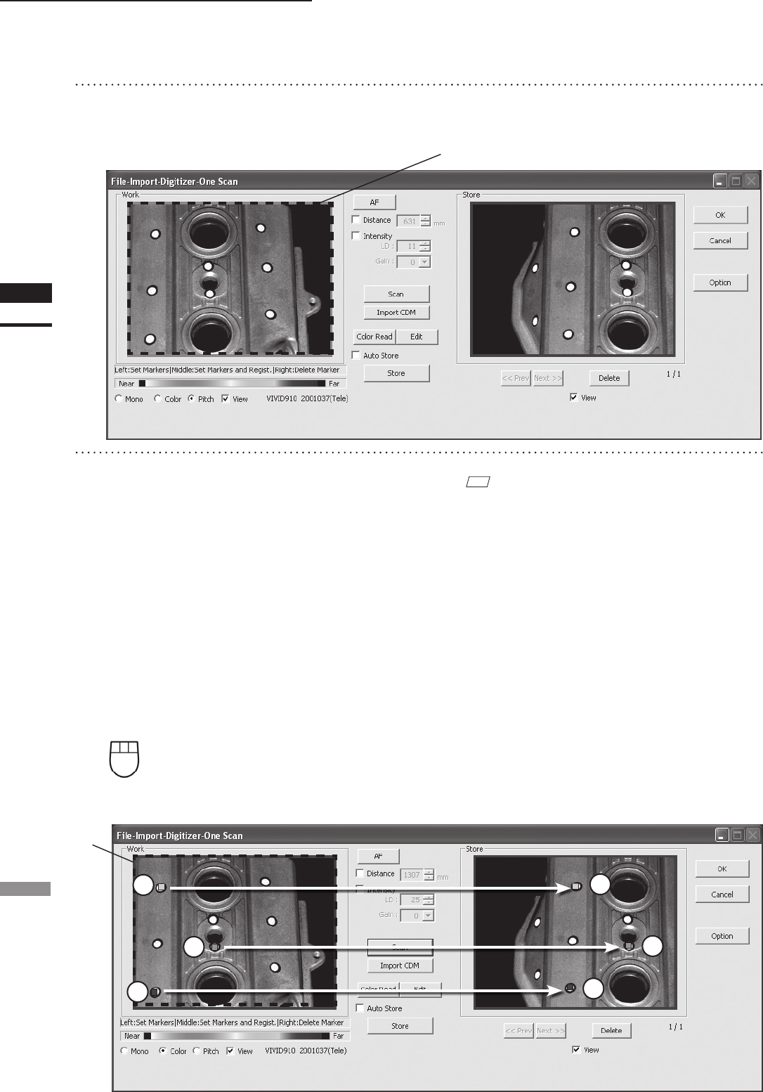
Designate three or more corresponding
points. Set the corresponding points in
the work window and then store win-
dow alternately. When the correspond-
ing points have been designated prop-
erly, the red frame will turn to blue.
• Each time corresponding points are designated,
registration among data is performed.
• If the [Auto Store] checkbox has been checked,
proceed to Step 12 after the corresponding points
are designated properly.
M
emo
Registration with 1 pair of corresponding points must be
used for objects with characteristic shape.
Since registration may not be performed successfully for
objects with non-characteristic shape (e.g. at planes, cy-
lindrical surfaces), using 3 pairs of corresponding points
is recommended
If desired points are set by left-clicking them,
registration will be performed each time 3 or
more pairs of corresponding points are set.
By using middle button or left button + [Shift]
button, registration can be performed when 1
or more pairs of corresponding points are set.
Left : Sets a point.
(Registration is performed using 3 or more pairs of corresponding points)
Middle : Sets a point.
([Shift] + Left) (Registration is performed using 1 or more pairs of corresponding points)
Right : Points in a Work window area or Store window area can be de-
leted by clicking them in the reverse order in which they were set.
3
5
2
4
6
Blue
1
10
Click on the [Scan] button.
At this time, the data in the Work window area
does not correspond to the one in the Store
window area, so a red frame is displayed.
RED