
Universal Remote User Manual
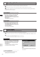
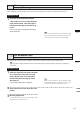
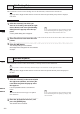


Table Of Contents
- Safety Symbols
- Notes on this Manual
- Trademarks
- About This Manual and Related Documents
- Safety Precautions
- Software Restrictions
- Notes On Use
- Notes On Storage
- Contents
- Conventions for Command Reference (Chapter 2)
- Chapter 1 Forward
- Chapter 2 Command Reference
- File Menu
- File – New
- File – Open
- File – Save – Elements
- File – Save – Scene
- File – Save as – Elements
- File – Save as – Scene
- File – Import – Elements
- File – Import – Digitizer – One Scan
- File – Import – Digitizer – Step Scan
- File – Import – Digitizer – One Scan
- File – Import – Digitizer – Step Scan
- File – Import – Digitizer – PC Card
- File – Import – Digitizer – PC Card
- File – Import – Digitizer – One Scan
- File – Import – Digitizer – Step Scan
- File – Import – Digitizer – PC Card
- File – Import – Digitizer – One Scan
- File – Import – Digitizer – Step Scan
- File – Import – Digitizer – Easy Align
- File – Import – Digitizer – PSC-1
- File – Export – Elements
- File – Export – Images
- File – Remove Elements
- File – Preferences
- File – Select Digitizer
- File – Exit
- View Menu
- Select Menu
- Edit Menu
- Build Menu
- Build – Registration – Initial – Manual
- Build – Registration – Initial – Auto
- Build – Registration – Fine – Elements
- Build – Registration – Fine – Points
- Build – Move – Points
- Build – Move – Elements
- Build – Move – To Origin
- Build – Move – To X-Y-Z
- Build – Rotate – Elements
- Build – Merge
- Build – Fill Holes – Manual
- Build – Fill Holes – Auto
- Build – Smooth – Element
- Build – Smooth – Points
- Build – Subsample – Uniformly – Element
- Build – Subsample – Uniformly – Points
- Build – Subsample – Adaptively – Element
- Build – Subsample – Adaptively – Points
- Build – Modify – Element
- Build – Modify – Points
- Build – Subdivision – Element
- Build – Subdivision – Points
- Build – Triangulate – Elements
- Build – Triangulate – Polygons
- Build – Texture Blending
- Build – Check Polygons – Element
- Build – Check Polygons – Polygons
- Info Menu
- Window Menu
- Tool Menu
- Pop-up Menus in Element View Window
- View Mode – Front/Right/Left/Back/Top/Bottom/Isometric/Perspective
- Rendering Mode – Wireframe/Shading/Texture Mapping/Wireframe+ Shading/Wireframe + Texture Mapping
- Show Vertex/Hide Vertex
- Show Normal/Hide Normal
- Show Axis/Hide Axis
- Smooth Shading/Flat Shading
- Select element from window
- Create clone window
- Close window
- Property
- Pop-up Menus in Element List
- Pop-up Menus in Image Window
- File Menu
- Chapter 3 Appendix
254
Chapter
2
Pop-up Menus
in Image Window
9i
910
900
700
300
Change Image
Changing the Color Image
This command is used to change the currently displayed color image with a new one.
Operating Procedure
1
From the pop-up menu, click [Change
Image].
A sub menu will appear.
2
Select the desired color image.
The currently displayed color image will be
replaced with the selected one.
Overlay
Displaying Wireframe on a Color Image
This command is used to overlay wireframe on the currently displayed color image.
Operating Procedure
1
From the pop-up menu, click [Overlay].
Wireframe will be overlaid on the element im-
age.
Note
However,ifthecurrentlydisplayedcolorimageisthe
onethathasbeenaddedtothedatatakenbytheVIVID
(VI)seriesdigitizer,nowireframewillbedisplayed.
Zoom In
Changing the Color Image
This command is used to enlarge the currently displayed color image.
Operating Procedure
1
From the pop-up menu, click [Zoom In].
The color image will be enlarged in steps by
the following magnication ratio each time this
command is selected.
1/12, 1/8, 1/6, 1/4, 1/3, 1/2, 2/3, 1, 2, 3, 4, 5, 6,
7 and 8
• If the image is enlarged beyond the image win-
dow, a scroll bar will appear.