
Universal Remote User Manual
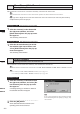
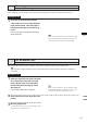
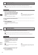


Table Of Contents
- Safety Symbols
- Notes on this Manual
- Trademarks
- About This Manual and Related Documents
- Safety Precautions
- Software Restrictions
- Notes On Use
- Notes On Storage
- Contents
- Conventions for Command Reference (Chapter 2)
- Chapter 1 Forward
- Chapter 2 Command Reference
- File Menu
- File – New
- File – Open
- File – Save – Elements
- File – Save – Scene
- File – Save as – Elements
- File – Save as – Scene
- File – Import – Elements
- File – Import – Digitizer – One Scan
- File – Import – Digitizer – Step Scan
- File – Import – Digitizer – One Scan
- File – Import – Digitizer – Step Scan
- File – Import – Digitizer – PC Card
- File – Import – Digitizer – PC Card
- File – Import – Digitizer – One Scan
- File – Import – Digitizer – Step Scan
- File – Import – Digitizer – PC Card
- File – Import – Digitizer – One Scan
- File – Import – Digitizer – Step Scan
- File – Import – Digitizer – Easy Align
- File – Import – Digitizer – PSC-1
- File – Export – Elements
- File – Export – Images
- File – Remove Elements
- File – Preferences
- File – Select Digitizer
- File – Exit
- View Menu
- Select Menu
- Edit Menu
- Build Menu
- Build – Registration – Initial – Manual
- Build – Registration – Initial – Auto
- Build – Registration – Fine – Elements
- Build – Registration – Fine – Points
- Build – Move – Points
- Build – Move – Elements
- Build – Move – To Origin
- Build – Move – To X-Y-Z
- Build – Rotate – Elements
- Build – Merge
- Build – Fill Holes – Manual
- Build – Fill Holes – Auto
- Build – Smooth – Element
- Build – Smooth – Points
- Build – Subsample – Uniformly – Element
- Build – Subsample – Uniformly – Points
- Build – Subsample – Adaptively – Element
- Build – Subsample – Adaptively – Points
- Build – Modify – Element
- Build – Modify – Points
- Build – Subdivision – Element
- Build – Subdivision – Points
- Build – Triangulate – Elements
- Build – Triangulate – Polygons
- Build – Texture Blending
- Build – Check Polygons – Element
- Build – Check Polygons – Polygons
- Info Menu
- Window Menu
- Tool Menu
- Pop-up Menus in Element View Window
- View Mode – Front/Right/Left/Back/Top/Bottom/Isometric/Perspective
- Rendering Mode – Wireframe/Shading/Texture Mapping/Wireframe+ Shading/Wireframe + Texture Mapping
- Show Vertex/Hide Vertex
- Show Normal/Hide Normal
- Show Axis/Hide Axis
- Smooth Shading/Flat Shading
- Select element from window
- Create clone window
- Close window
- Property
- Pop-up Menus in Element List
- Pop-up Menus in Image Window
- File Menu
- Chapter 3 Appendix
251
Chapter
2
Pop-up Menus
in Element List
9i
910
900
700
300
View Image
Displaying Color Images
This command is used to display color images of the element(s) currently selected in the element list.
Operating Procedure
1
Click the desired element(s) whose
color images are to be shown with the
right mouse button, and select [View
Image] from the pop-up menu that ap-
pears.
The color images of the selected element(s)
will be displayed.
Set Wireframe Color
Changing Wireframe Color
This command is used to set the wireframe color for the element(s) selected in the element list.
Note
Ifapop-upmenuisdisplayedwithoutelementsselectedintheelementlist,[SetWireframeColor]willnotbedisplayed
inthemenu.
Operating Procedure
1
Click the element(s) for which you want
to set wireframe color with the right
mouse button, and select [Set Wire-
frame Color] from the pop-up menu
that appears.
A color palette dialog box will appear.
M
emo
If two or more elements have been selected by clicking
them while holding down the [Shift] or [Ctrl] key, the
color images for those elements can be displayed.
M
emo
If two or more elements have been selected by clicking
them while holding down the [Shift] or [Ctrl] key, the
wireframe color for those elements can be set.
2
Select the desired color from the color
palette.
3
Click the [OK] button.
The wireframe color(s) for the selected element(s) will be
changed to the one selected at step 2.