
Universal Remote User Manual
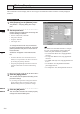
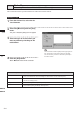
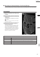
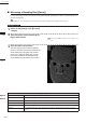
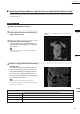
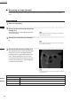
Table Of Contents
- Safety Symbols
- Notes on this Manual
- Trademarks
- About This Manual and Related Documents
- Safety Precautions
- Software Restrictions
- Notes On Use
- Notes On Storage
- Contents
- Conventions for Command Reference (Chapter 2)
- Chapter 1 Forward
- Chapter 2 Command Reference
- File Menu
- File – New
- File – Open
- File – Save – Elements
- File – Save – Scene
- File – Save as – Elements
- File – Save as – Scene
- File – Import – Elements
- File – Import – Digitizer – One Scan
- File – Import – Digitizer – Step Scan
- File – Import – Digitizer – One Scan
- File – Import – Digitizer – Step Scan
- File – Import – Digitizer – PC Card
- File – Import – Digitizer – PC Card
- File – Import – Digitizer – One Scan
- File – Import – Digitizer – Step Scan
- File – Import – Digitizer – PC Card
- File – Import – Digitizer – One Scan
- File – Import – Digitizer – Step Scan
- File – Import – Digitizer – Easy Align
- File – Import – Digitizer – PSC-1
- File – Export – Elements
- File – Export – Images
- File – Remove Elements
- File – Preferences
- File – Select Digitizer
- File – Exit
- View Menu
- Select Menu
- Edit Menu
- Build Menu
- Build – Registration – Initial – Manual
- Build – Registration – Initial – Auto
- Build – Registration – Fine – Elements
- Build – Registration – Fine – Points
- Build – Move – Points
- Build – Move – Elements
- Build – Move – To Origin
- Build – Move – To X-Y-Z
- Build – Rotate – Elements
- Build – Merge
- Build – Fill Holes – Manual
- Build – Fill Holes – Auto
- Build – Smooth – Element
- Build – Smooth – Points
- Build – Subsample – Uniformly – Element
- Build – Subsample – Uniformly – Points
- Build – Subsample – Adaptively – Element
- Build – Subsample – Adaptively – Points
- Build – Modify – Element
- Build – Modify – Points
- Build – Subdivision – Element
- Build – Subdivision – Points
- Build – Triangulate – Elements
- Build – Triangulate – Polygons
- Build – Texture Blending
- Build – Check Polygons – Element
- Build – Check Polygons – Polygons
- Info Menu
- Window Menu
- Tool Menu
- Pop-up Menus in Element View Window
- View Mode – Front/Right/Left/Back/Top/Bottom/Isometric/Perspective
- Rendering Mode – Wireframe/Shading/Texture Mapping/Wireframe+ Shading/Wireframe + Texture Mapping
- Show Vertex/Hide Vertex
- Show Normal/Hide Normal
- Show Axis/Hide Axis
- Smooth Shading/Flat Shading
- Select element from window
- Create clone window
- Close window
- Property
- Pop-up Menus in Element List
- Pop-up Menus in Image Window
- File Menu
- Chapter 3 Appendix
238
Chapter
2
Tool
Menu
9i
910
900
700
300
n Measuring an Angle ([Angle])
Use the following procedure to measure the angle formed by three specied points on the selected ele-
ment.
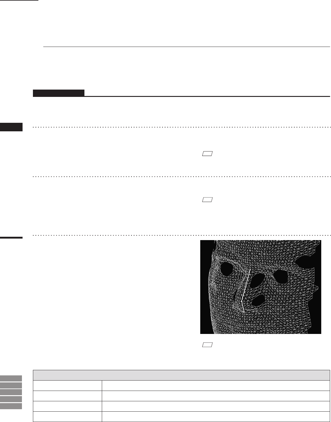
Parameters Returned When Measuring an Angle ([Angle])
Angle
Angle formed by the three points, in degrees. (White lines in an element view window.)
Point 1
Coordinates of the rst specied point. (Yellow point in an element view window.)
Point 2
Coordinates of the second specied point. (Yellow point in an element view window.)
Point 3
Coordinates of the third specied point. (Yellow point in an element view window.)
Operating Procedure
1
Check on the [Angle].
2
Specify the first point on the element by
clicking on it.
The specied point will be displayed in an ele-
ment view window.
M
emo
If you want to redo the point specifying, click the Right
mouse button at anywhere.
3
Specify the second point by clicking on
it.
M
emo
If you want to redo the point specifying, click the Right
mouse button at anywhere.
4
Specify the third point by clicking on it.
The angle dened by the three specied points
is calculated, and the calculated results will
be displayed in the upper-right window of the
[Tool – Measure] dialog box, and two lines -
connecting the rst point to second point and
second point to third point - will be displayed
in an element view window.
M
emo
To calculate the next angle, click the Right mouse button
on the next point.
Tool – Measure