
Universal Remote User Manual
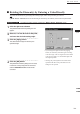
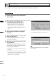
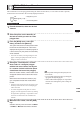
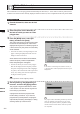
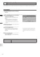
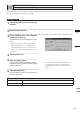
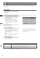
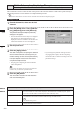
Table Of Contents
- Safety Symbols
- Notes on this Manual
- Trademarks
- About This Manual and Related Documents
- Safety Precautions
- Software Restrictions
- Notes On Use
- Notes On Storage
- Contents
- Conventions for Command Reference (Chapter 2)
- Chapter 1 Forward
- Chapter 2 Command Reference
- File Menu
- File – New
- File – Open
- File – Save – Elements
- File – Save – Scene
- File – Save as – Elements
- File – Save as – Scene
- File – Import – Elements
- File – Import – Digitizer – One Scan
- File – Import – Digitizer – Step Scan
- File – Import – Digitizer – One Scan
- File – Import – Digitizer – Step Scan
- File – Import – Digitizer – PC Card
- File – Import – Digitizer – PC Card
- File – Import – Digitizer – One Scan
- File – Import – Digitizer – Step Scan
- File – Import – Digitizer – PC Card
- File – Import – Digitizer – One Scan
- File – Import – Digitizer – Step Scan
- File – Import – Digitizer – Easy Align
- File – Import – Digitizer – PSC-1
- File – Export – Elements
- File – Export – Images
- File – Remove Elements
- File – Preferences
- File – Select Digitizer
- File – Exit
- View Menu
- Select Menu
- Edit Menu
- Build Menu
- Build – Registration – Initial – Manual
- Build – Registration – Initial – Auto
- Build – Registration – Fine – Elements
- Build – Registration – Fine – Points
- Build – Move – Points
- Build – Move – Elements
- Build – Move – To Origin
- Build – Move – To X-Y-Z
- Build – Rotate – Elements
- Build – Merge
- Build – Fill Holes – Manual
- Build – Fill Holes – Auto
- Build – Smooth – Element
- Build – Smooth – Points
- Build – Subsample – Uniformly – Element
- Build – Subsample – Uniformly – Points
- Build – Subsample – Adaptively – Element
- Build – Subsample – Adaptively – Points
- Build – Modify – Element
- Build – Modify – Points
- Build – Subdivision – Element
- Build – Subdivision – Points
- Build – Triangulate – Elements
- Build – Triangulate – Polygons
- Build – Texture Blending
- Build – Check Polygons – Element
- Build – Check Polygons – Polygons
- Info Menu
- Window Menu
- Tool Menu
- Pop-up Menus in Element View Window
- View Mode – Front/Right/Left/Back/Top/Bottom/Isometric/Perspective
- Rendering Mode – Wireframe/Shading/Texture Mapping/Wireframe+ Shading/Wireframe + Texture Mapping
- Show Vertex/Hide Vertex
- Show Normal/Hide Normal
- Show Axis/Hide Axis
- Smooth Shading/Flat Shading
- Select element from window
- Create clone window
- Close window
- Property
- Pop-up Menus in Element List
- Pop-up Menus in Image Window
- File Menu
- Chapter 3 Appendix
202
Chapter
2
Build
Menu
9i
910
900
700
300
Build – Fill Holes – Auto
Filling Holes Automatically
This command is to create polygon data automatically for the holes (i.e. areas where no data is present) locat-
ed in the area selected in the currently displayed element. However, some complicated holes may not be lled.
Operating Procedure
1
From the element list, select one desired
element.
2
Select the points on the boundary of
the hole for which you want to create
polygon data.
3
From the [Build] menu, select [Fill
Holes] and then click [Auto].
The system will search for holes present within
the area of the selected points. A bar will be
displayed during search to indicate progress. If
a hole is found, only the points on its boundary
will be selected.
• If no holes are found, a message dialog box will
appear. Clicking the [OK] button will close the
dialog box and exit the menu.
All the element view windows will be hidden,
and the temporary window and [Build-Fill
Holes-Auto] dialog box will appear.
• The hole for which you want to create polygon
data will be displayed in the temporary window.
The points comprising the hole will be highlight-
ed (yellow). The selected holes will be processed
one by one, starting with the hole composed of
the largest number of points.
M
emo
If the number of remaining holes (Number of holes) is
1, the [OK] button will be displayed instead of the [Next
Hole] button.
Note
Itisnotpossibletoclosethetemporarywindow.
4
Set the [Flatness] and [Algorithm] pa-
rameters, and click the [Apply] button.
The program merges the elements to create
a new element. The new element is given the
name that you just entered.
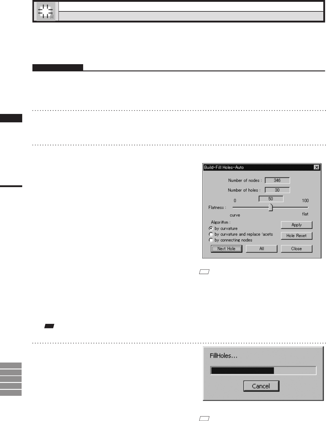
A progress bar shows the progress while
the ll is being carried out. If you click the
progress bar’s [Cancel] button, the program
suspends ll processing and displays a dialog
showing results up to that moment.
M
emo
The program retains the ll data generated up to the time
when you clicked the [Cancel] button. If you wish to
resume the ll operation, click the [All] button. Filling
will then continue from the hole at which the operation
was suspended.