
Universal Remote User Manual
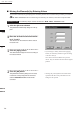
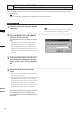
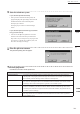
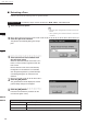
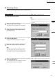
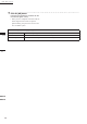
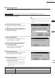
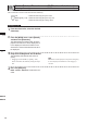
Table Of Contents
- Safety Symbols
- Notes on this Manual
- Trademarks
- About This Manual and Related Documents
- Safety Precautions
- Software Restrictions
- Notes On Use
- Notes On Storage
- Contents
- Conventions for Command Reference (Chapter 2)
- Chapter 1 Forward
- Chapter 2 Command Reference
- File Menu
- File – New
- File – Open
- File – Save – Elements
- File – Save – Scene
- File – Save as – Elements
- File – Save as – Scene
- File – Import – Elements
- File – Import – Digitizer – One Scan
- File – Import – Digitizer – Step Scan
- File – Import – Digitizer – One Scan
- File – Import – Digitizer – Step Scan
- File – Import – Digitizer – PC Card
- File – Import – Digitizer – PC Card
- File – Import – Digitizer – One Scan
- File – Import – Digitizer – Step Scan
- File – Import – Digitizer – PC Card
- File – Import – Digitizer – One Scan
- File – Import – Digitizer – Step Scan
- File – Import – Digitizer – Easy Align
- File – Import – Digitizer – PSC-1
- File – Export – Elements
- File – Export – Images
- File – Remove Elements
- File – Preferences
- File – Select Digitizer
- File – Exit
- View Menu
- Select Menu
- Edit Menu
- Build Menu
- Build – Registration – Initial – Manual
- Build – Registration – Initial – Auto
- Build – Registration – Fine – Elements
- Build – Registration – Fine – Points
- Build – Move – Points
- Build – Move – Elements
- Build – Move – To Origin
- Build – Move – To X-Y-Z
- Build – Rotate – Elements
- Build – Merge
- Build – Fill Holes – Manual
- Build – Fill Holes – Auto
- Build – Smooth – Element
- Build – Smooth – Points
- Build – Subsample – Uniformly – Element
- Build – Subsample – Uniformly – Points
- Build – Subsample – Adaptively – Element
- Build – Subsample – Adaptively – Points
- Build – Modify – Element
- Build – Modify – Points
- Build – Subdivision – Element
- Build – Subdivision – Points
- Build – Triangulate – Elements
- Build – Triangulate – Polygons
- Build – Texture Blending
- Build – Check Polygons – Element
- Build – Check Polygons – Polygons
- Info Menu
- Window Menu
- Tool Menu
- Pop-up Menus in Element View Window
- View Mode – Front/Right/Left/Back/Top/Bottom/Isometric/Perspective
- Rendering Mode – Wireframe/Shading/Texture Mapping/Wireframe+ Shading/Wireframe + Texture Mapping
- Show Vertex/Hide Vertex
- Show Normal/Hide Normal
- Show Axis/Hide Axis
- Smooth Shading/Flat Shading
- Select element from window
- Create clone window
- Close window
- Property
- Pop-up Menus in Element List
- Pop-up Menus in Image Window
- File Menu
- Chapter 3 Appendix
194
Chapter
2
Build
Menu
9i
910
900
700
300
n Extracting a Face
Extract a face from the selected points as explained below.
Operating Procedure
The following steps must be carried out in Build – Move – To X-Y-Z mode.
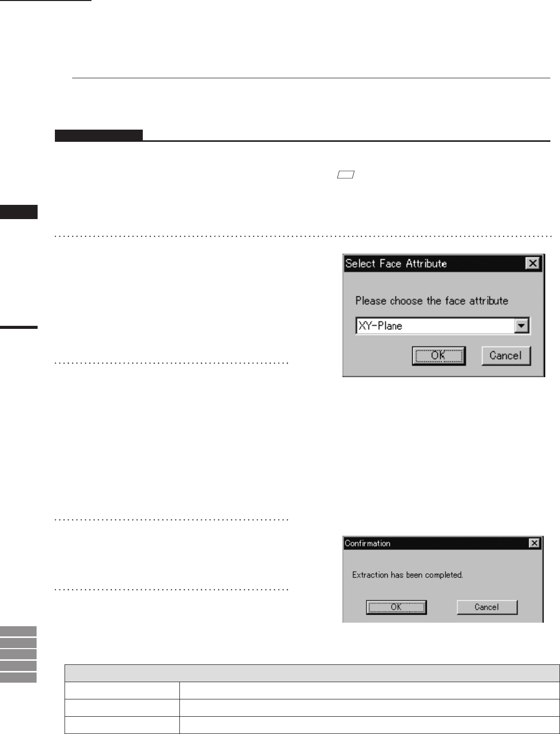
Parameters for [Select Face Attribute] Dialog Box
XY-Plane
Generates a XY plane based on the selected points.
YZ-Plane
Generates a YZ plane based on the selected points.
ZX-Plane
Generates a ZX plane based on the selected points.
1
Select the desired points.
M
emo
• Select the points using the Select and View menu com-
mands.
• After operation, please cancel the Select or View menu
command.
2
Click the right mouse button.
The [Select Face Attribute] dialog box will ap-
pear.
3
Select the desired face attribute from
the pull-down menu.
When the selected attribute of the face is “XY-
Plane”, Z-Axis is made in agreement with the
face normal.
But the direction of the axis is calculated by
the algorithm. If the direction is not suitable,
click the [Reverse] button in [Conrmation(for
coordinate)] dialog box to reverse the axis
direction.
4
Click the [OK] button.
The generated face will be displayed, and the
[Conrmation] dialog box will appear.
5
Click the [OK] button.
Proceed to the extraction procedure for the
next element (point or line).
Build – Move – To X-Y-Z