
Universal Remote User Manual
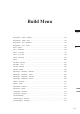
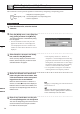
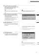
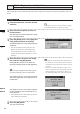
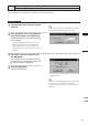
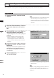
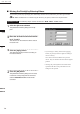
Table Of Contents
- Safety Symbols
- Notes on this Manual
- Trademarks
- About This Manual and Related Documents
- Safety Precautions
- Software Restrictions
- Notes On Use
- Notes On Storage
- Contents
- Conventions for Command Reference (Chapter 2)
- Chapter 1 Forward
- Chapter 2 Command Reference
- File Menu
- File – New
- File – Open
- File – Save – Elements
- File – Save – Scene
- File – Save as – Elements
- File – Save as – Scene
- File – Import – Elements
- File – Import – Digitizer – One Scan
- File – Import – Digitizer – Step Scan
- File – Import – Digitizer – One Scan
- File – Import – Digitizer – Step Scan
- File – Import – Digitizer – PC Card
- File – Import – Digitizer – PC Card
- File – Import – Digitizer – One Scan
- File – Import – Digitizer – Step Scan
- File – Import – Digitizer – PC Card
- File – Import – Digitizer – One Scan
- File – Import – Digitizer – Step Scan
- File – Import – Digitizer – Easy Align
- File – Import – Digitizer – PSC-1
- File – Export – Elements
- File – Export – Images
- File – Remove Elements
- File – Preferences
- File – Select Digitizer
- File – Exit
- View Menu
- Select Menu
- Edit Menu
- Build Menu
- Build – Registration – Initial – Manual
- Build – Registration – Initial – Auto
- Build – Registration – Fine – Elements
- Build – Registration – Fine – Points
- Build – Move – Points
- Build – Move – Elements
- Build – Move – To Origin
- Build – Move – To X-Y-Z
- Build – Rotate – Elements
- Build – Merge
- Build – Fill Holes – Manual
- Build – Fill Holes – Auto
- Build – Smooth – Element
- Build – Smooth – Points
- Build – Subsample – Uniformly – Element
- Build – Subsample – Uniformly – Points
- Build – Subsample – Adaptively – Element
- Build – Subsample – Adaptively – Points
- Build – Modify – Element
- Build – Modify – Points
- Build – Subdivision – Element
- Build – Subdivision – Points
- Build – Triangulate – Elements
- Build – Triangulate – Polygons
- Build – Texture Blending
- Build – Check Polygons – Element
- Build – Check Polygons – Polygons
- Info Menu
- Window Menu
- Tool Menu
- Pop-up Menus in Element View Window
- View Mode – Front/Right/Left/Back/Top/Bottom/Isometric/Perspective
- Rendering Mode – Wireframe/Shading/Texture Mapping/Wireframe+ Shading/Wireframe + Texture Mapping
- Show Vertex/Hide Vertex
- Show Normal/Hide Normal
- Show Axis/Hide Axis
- Smooth Shading/Flat Shading
- Select element from window
- Create clone window
- Close window
- Property
- Pop-up Menus in Element List
- Pop-up Menus in Image Window
- File Menu
- Chapter 3 Appendix
183
Chapter
2
Build
Menu
9i
910
900
700
300
6
To delete a pair of corresponding
points, click either of those points with
the middle button ([Shift] + Left).
The marker will be deleted.
M
emo
Even when designating corresponding points, they can
be deleted by clicking with the middle button ([Shift] +
Left).
Note
Analarmwillbeheardifapointotherthosedesignated
isclickedwiththemiddlebutton([Shift]+Left).
7
After designation of corresponding
points has been completed, click the
right mouse button.
The initial registration will start, and the result
will be displayed in the window.
A message dialog box asking whether the
result is satisfactory will appear.
8
Click the [OK] button.
The program executes ne registration, and
opens a dialog asking whether the results are
satisfactory.
• If you click [Retry], the program will reopen the
temporary windows so that you can reset the cor-
respondences again.
• If you click [Cancel], ne registration will be
canceled and closes the menu.
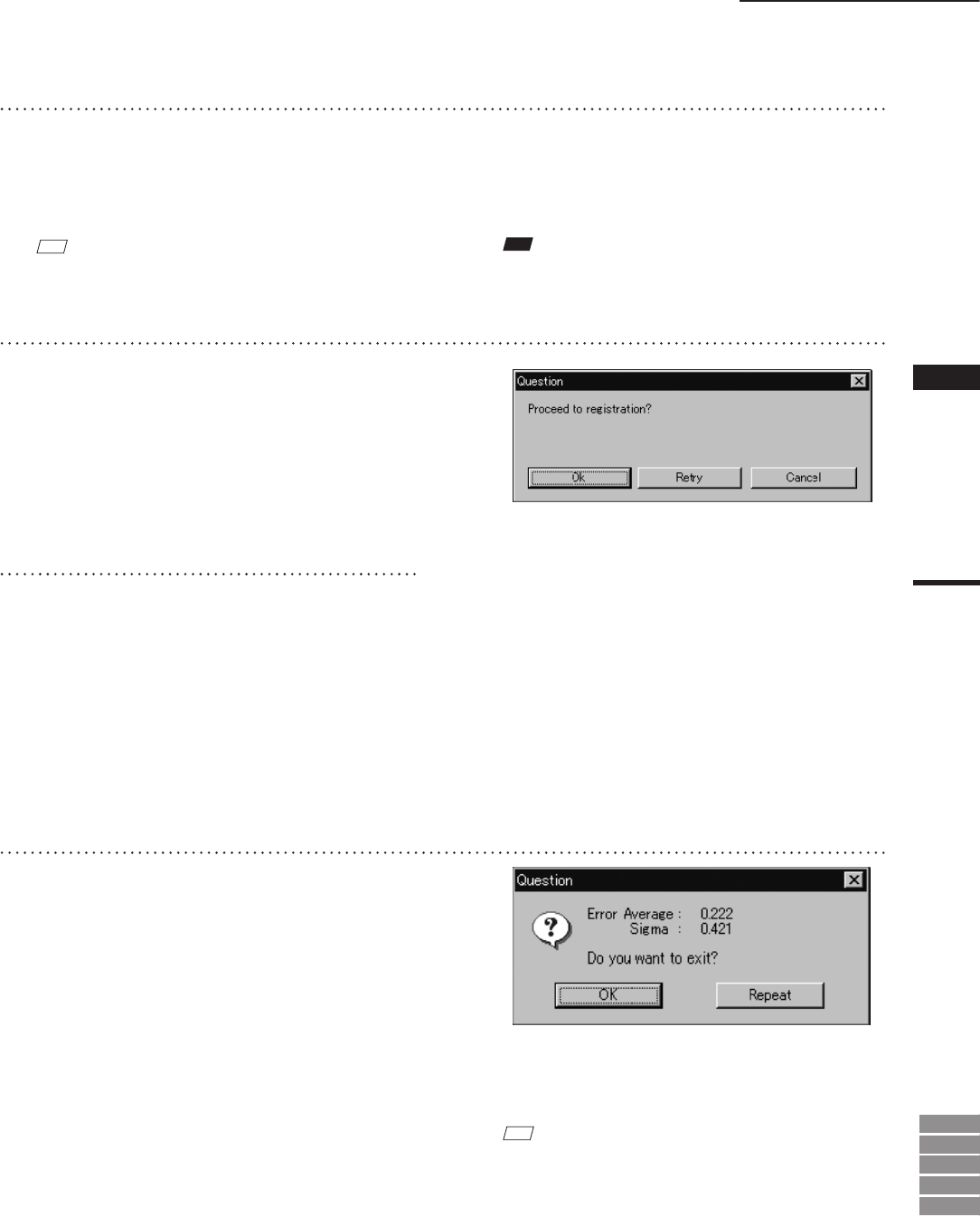
9
Click the [OK] button.
All temporary registration windows close, and
the program reopens the windows that were
on display when you started the command.
• To continue ne registration processing, click the
[Repeat] button.
M
emo
The [Error Average] and [Sigma] values are indicators of
the correctness of the registration (the alignment).
In general, the closer to zero they are, the more accurate
alignment is.
Build – Registration – Initial – Manual