
Universal Remote User Manual
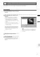
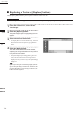
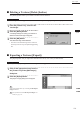
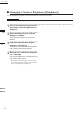
Table Of Contents
- Safety Symbols
- Notes on this Manual
- Trademarks
- About This Manual and Related Documents
- Safety Precautions
- Software Restrictions
- Notes On Use
- Notes On Storage
- Contents
- Conventions for Command Reference (Chapter 2)
- Chapter 1 Forward
- Chapter 2 Command Reference
- File Menu
- File – New
- File – Open
- File – Save – Elements
- File – Save – Scene
- File – Save as – Elements
- File – Save as – Scene
- File – Import – Elements
- File – Import – Digitizer – One Scan
- File – Import – Digitizer – Step Scan
- File – Import – Digitizer – One Scan
- File – Import – Digitizer – Step Scan
- File – Import – Digitizer – PC Card
- File – Import – Digitizer – PC Card
- File – Import – Digitizer – One Scan
- File – Import – Digitizer – Step Scan
- File – Import – Digitizer – PC Card
- File – Import – Digitizer – One Scan
- File – Import – Digitizer – Step Scan
- File – Import – Digitizer – Easy Align
- File – Import – Digitizer – PSC-1
- File – Export – Elements
- File – Export – Images
- File – Remove Elements
- File – Preferences
- File – Select Digitizer
- File – Exit
- View Menu
- Select Menu
- Edit Menu
- Build Menu
- Build – Registration – Initial – Manual
- Build – Registration – Initial – Auto
- Build – Registration – Fine – Elements
- Build – Registration – Fine – Points
- Build – Move – Points
- Build – Move – Elements
- Build – Move – To Origin
- Build – Move – To X-Y-Z
- Build – Rotate – Elements
- Build – Merge
- Build – Fill Holes – Manual
- Build – Fill Holes – Auto
- Build – Smooth – Element
- Build – Smooth – Points
- Build – Subsample – Uniformly – Element
- Build – Subsample – Uniformly – Points
- Build – Subsample – Adaptively – Element
- Build – Subsample – Adaptively – Points
- Build – Modify – Element
- Build – Modify – Points
- Build – Subdivision – Element
- Build – Subdivision – Points
- Build – Triangulate – Elements
- Build – Triangulate – Polygons
- Build – Texture Blending
- Build – Check Polygons – Element
- Build – Check Polygons – Polygons
- Info Menu
- Window Menu
- Tool Menu
- Pop-up Menus in Element View Window
- View Mode – Front/Right/Left/Back/Top/Bottom/Isometric/Perspective
- Rendering Mode – Wireframe/Shading/Texture Mapping/Wireframe+ Shading/Wireframe + Texture Mapping
- Show Vertex/Hide Vertex
- Show Normal/Hide Normal
- Show Axis/Hide Axis
- Smooth Shading/Flat Shading
- Select element from window
- Create clone window
- Close window
- Property
- Pop-up Menus in Element List
- Pop-up Menus in Image Window
- File Menu
- Chapter 3 Appendix
173
Chapter
2
Edit
Menu
9i
910
900
700
300
5
Repeat step 4 until six or more pairs of
corresponding points are designated.
The order of designating points in the rst and
second image windows for the rst pair can
differ from that for the second pair.
M
emo
For satisfactory registration of the images, approximately
12 pairs of corresponding points must be designated.
6
To delete a pair of corresponding
points, click either of those points with
the left mouse button while holding
down the [Shift] button.
The pair of corresponding points will be de-
leted.
• Even when designating corresponding points,
they can be deleted by clicking with the left
mouse button while holding down the [Shift] but-
ton.
• An alarm will be heard if a point other those
designated is clicked with the left mouse button
while holding down the [Shift] button.
7
Click the [Preview] button.
A temporary window will appear, showing the
preview image.
• The temporary window is a Perspective view, and
is displayed in texture mapping mode.
• Dragging while holding down the left mouse
button inside the preview window will rotate the
camera.
Note
• Anerrormessagewillappearifonlyveorlesspairs
ofpointshavebeendesignated.
• Anerrormessagewillappearifcalculationcannotbe
madebasedonthedesignatedpoints.
M
emo
If registration is not satisfactory, designate more cor-
responding points or delete unsatisfactory corresponding
points.
8
Click the [OK] button.
A new image will be added to the element.
• All the image windows, [Point Set] dialog box
and the temporary window (if it is open) will
close, and the [Edit-Image] dialog box will ap-
pear. All the element view windows will also
appear.
The added image will be displayed in the [Tex-
ture List] in the [Edit-Image] dialog box.
Edit – Images