
Universal Remote User Manual
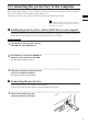
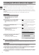
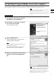
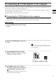
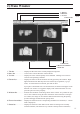
Table Of Contents
- Safety Symbols
- Notes on this Manual
- Trademarks
- About This Manual and Related Documents
- Safety Precautions
- Software Restrictions
- Notes On Use
- Notes On Storage
- Contents
- Conventions for Command Reference (Chapter 2)
- Chapter 1 Forward
- Chapter 2 Command Reference
- File Menu
- File – New
- File – Open
- File – Save – Elements
- File – Save – Scene
- File – Save as – Elements
- File – Save as – Scene
- File – Import – Elements
- File – Import – Digitizer – One Scan
- File – Import – Digitizer – Step Scan
- File – Import – Digitizer – One Scan
- File – Import – Digitizer – Step Scan
- File – Import – Digitizer – PC Card
- File – Import – Digitizer – PC Card
- File – Import – Digitizer – One Scan
- File – Import – Digitizer – Step Scan
- File – Import – Digitizer – PC Card
- File – Import – Digitizer – One Scan
- File – Import – Digitizer – Step Scan
- File – Import – Digitizer – Easy Align
- File – Import – Digitizer – PSC-1
- File – Export – Elements
- File – Export – Images
- File – Remove Elements
- File – Preferences
- File – Select Digitizer
- File – Exit
- View Menu
- Select Menu
- Edit Menu
- Build Menu
- Build – Registration – Initial – Manual
- Build – Registration – Initial – Auto
- Build – Registration – Fine – Elements
- Build – Registration – Fine – Points
- Build – Move – Points
- Build – Move – Elements
- Build – Move – To Origin
- Build – Move – To X-Y-Z
- Build – Rotate – Elements
- Build – Merge
- Build – Fill Holes – Manual
- Build – Fill Holes – Auto
- Build – Smooth – Element
- Build – Smooth – Points
- Build – Subsample – Uniformly – Element
- Build – Subsample – Uniformly – Points
- Build – Subsample – Adaptively – Element
- Build – Subsample – Adaptively – Points
- Build – Modify – Element
- Build – Modify – Points
- Build – Subdivision – Element
- Build – Subdivision – Points
- Build – Triangulate – Elements
- Build – Triangulate – Polygons
- Build – Texture Blending
- Build – Check Polygons – Element
- Build – Check Polygons – Polygons
- Info Menu
- Window Menu
- Tool Menu
- Pop-up Menus in Element View Window
- View Mode – Front/Right/Left/Back/Top/Bottom/Isometric/Perspective
- Rendering Mode – Wireframe/Shading/Texture Mapping/Wireframe+ Shading/Wireframe + Texture Mapping
- Show Vertex/Hide Vertex
- Show Normal/Hide Normal
- Show Axis/Hide Axis
- Smooth Shading/Flat Shading
- Select element from window
- Create clone window
- Close window
- Property
- Pop-up Menus in Element List
- Pop-up Menus in Image Window
- File Menu
- Chapter 3 Appendix

5)
ConnectingtheVIVIDdigitizertothecomputer
WhentheVIVIDdigitizerwillbecontrolledfromPolygonEditingTool,connecttheVIVIDdigitizertothe
computerrst,andthenstartupPolygonEditingTool.
ThersttimetheVIVIDdigitizerisconnectedtothecomputer,itisnecessaryforthecomputertorecognize
theVIVIDdigitizerasanexternaldevice.
Performoperationsaccordingtothefollowingprocedure.
nConnectingtheVIVIDdigitizertothecomputer
Inorderfortheprotectkeytoberecognizedbythecorrespondingdriversoftware,itisnecessarytoinstallthe
driversoftwareonthecomputerbeforeconnectingtheprotectkeytothecomputer.
Operating Procedure
1
Turn the POWER switch of the comput-
er OFF.
2
Connect the VIVID digitizer to the com-
puter.
Memo
FordetailsonhowtoconnecttheVIVIDdigitizertothe
computer,refertotheinstructionmanualofeachmodel
oftheVIVIDdigitizer.
3
Set the POWER switch of the VIVID
digitizer to ON (set switch to “I” mark).
Initializing of the digitizer will start.
4
After MENU appears in the finder of
the digitizer, switch on the computer to
start the Windows operating system.
Note
The POWER switch of the digitizer should be set to ON
rst before switching on the computer.
Chapter
1
Preparations
13
0/7%2
!# ).
3#3)