
Universal Remote User Manual
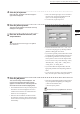
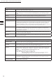
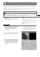
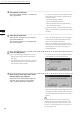
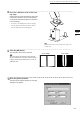
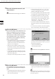
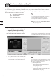
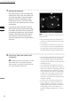
Table Of Contents
- Safety Symbols
- Notes on this Manual
- Trademarks
- About This Manual and Related Documents
- Safety Precautions
- Software Restrictions
- Notes On Use
- Notes On Storage
- Contents
- Conventions for Command Reference (Chapter 2)
- Chapter 1 Forward
- Chapter 2 Command Reference
- File Menu
- File – New
- File – Open
- File – Save – Elements
- File – Save – Scene
- File – Save as – Elements
- File – Save as – Scene
- File – Import – Elements
- File – Import – Digitizer – One Scan
- File – Import – Digitizer – Step Scan
- File – Import – Digitizer – One Scan
- File – Import – Digitizer – Step Scan
- File – Import – Digitizer – PC Card
- File – Import – Digitizer – PC Card
- File – Import – Digitizer – One Scan
- File – Import – Digitizer – Step Scan
- File – Import – Digitizer – PC Card
- File – Import – Digitizer – One Scan
- File – Import – Digitizer – Step Scan
- File – Import – Digitizer – Easy Align
- File – Import – Digitizer – PSC-1
- File – Export – Elements
- File – Export – Images
- File – Remove Elements
- File – Preferences
- File – Select Digitizer
- File – Exit
- View Menu
- Select Menu
- Edit Menu
- Build Menu
- Build – Registration – Initial – Manual
- Build – Registration – Initial – Auto
- Build – Registration – Fine – Elements
- Build – Registration – Fine – Points
- Build – Move – Points
- Build – Move – Elements
- Build – Move – To Origin
- Build – Move – To X-Y-Z
- Build – Rotate – Elements
- Build – Merge
- Build – Fill Holes – Manual
- Build – Fill Holes – Auto
- Build – Smooth – Element
- Build – Smooth – Points
- Build – Subsample – Uniformly – Element
- Build – Subsample – Uniformly – Points
- Build – Subsample – Adaptively – Element
- Build – Subsample – Adaptively – Points
- Build – Modify – Element
- Build – Modify – Points
- Build – Subdivision – Element
- Build – Subdivision – Points
- Build – Triangulate – Elements
- Build – Triangulate – Polygons
- Build – Texture Blending
- Build – Check Polygons – Element
- Build – Check Polygons – Polygons
- Info Menu
- Window Menu
- Tool Menu
- Pop-up Menus in Element View Window
- View Mode – Front/Right/Left/Back/Top/Bottom/Isometric/Perspective
- Rendering Mode – Wireframe/Shading/Texture Mapping/Wireframe+ Shading/Wireframe + Texture Mapping
- Show Vertex/Hide Vertex
- Show Normal/Hide Normal
- Show Axis/Hide Axis
- Smooth Shading/Flat Shading
- Select element from window
- Create clone window
- Close window
- Property
- Pop-up Menus in Element List
- Pop-up Menus in Image Window
- File Menu
- Chapter 3 Appendix
128
Chapter
2
File
Menu
910
File – Import – Digitizer – Easy Align
8
If necessary, adjust the marker corre-
spondences.
7
Click the [Scan] button.
The program takes the scan and displays the
resulting color image in the work window area
on the left of the dialog. It also automatically
detects the markers, and displays a single
character (0 to 9 or A to Y) for each “marker
ID” (0 to 34) in each location at which a marker
was detected.
If the program determines that the scanned
data is good enough for alignment processing,
the condition bar (under the work window) be-
comes blue and displays the “Good condition”
message. If the program determines that the
scan results are not good enough for align-
ment, the condition bar turns red and displays
“No good”.
M
emo
On the color image, areas that have no distance data are
displayed as black.
• When [Auto Marker Detection] checkbox is un-
checked, the automatic marker detection will not
be carried out.
• As an alternative to taking the scan at this time,
you can import a saved scan (CDM le) that was
previously taken with the VIVID 910. Just click
the [Import] button and load the appropriate le.
• If any of the detected marker IDs does not match
the corresponding marker on the actual object,
correct as follows: right-click the marker ID on
the image, and then enter the correct marker ID at
the dialog that opens.
• If any of the marker IDs displayed on the previ-
ously stored image (the image stored at step 9 be-
low) does not match the corresponding marker ID
displayed on the image scanned at step 7 above,
correct as follows: Left-click the mismatched ID
in either of these two images, and then left-click
on the correct corresponding marker ID in the
other image. The program will change the IDs so
that they are identical.
• To set up a “new” marker ID on images from
Step 7 on Step 9 in a location where there was
no physical marker on the object (or where the
program failed to detect a marker), left-click the
corresponding points in the two images. The
program will display a marker ID of “*” at these
points.
Note
Iftheconditionbar(undertheworkwindow)isred,this
meansthatthedataisnotyetsuitableforalignment.
Adjustthemarkercorrespondencesandtakeothersteps
asnecessaryuntilthebarbecomesblue.