
Universal Remote User Manual
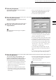
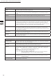
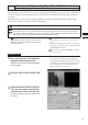
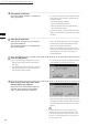
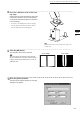
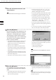
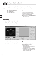
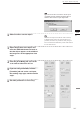
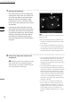
Table Of Contents
- Safety Symbols
- Notes on this Manual
- Trademarks
- About This Manual and Related Documents
- Safety Precautions
- Software Restrictions
- Notes On Use
- Notes On Storage
- Contents
- Conventions for Command Reference (Chapter 2)
- Chapter 1 Forward
- Chapter 2 Command Reference
- File Menu
- File – New
- File – Open
- File – Save – Elements
- File – Save – Scene
- File – Save as – Elements
- File – Save as – Scene
- File – Import – Elements
- File – Import – Digitizer – One Scan
- File – Import – Digitizer – Step Scan
- File – Import – Digitizer – One Scan
- File – Import – Digitizer – Step Scan
- File – Import – Digitizer – PC Card
- File – Import – Digitizer – PC Card
- File – Import – Digitizer – One Scan
- File – Import – Digitizer – Step Scan
- File – Import – Digitizer – PC Card
- File – Import – Digitizer – One Scan
- File – Import – Digitizer – Step Scan
- File – Import – Digitizer – Easy Align
- File – Import – Digitizer – PSC-1
- File – Export – Elements
- File – Export – Images
- File – Remove Elements
- File – Preferences
- File – Select Digitizer
- File – Exit
- View Menu
- Select Menu
- Edit Menu
- Build Menu
- Build – Registration – Initial – Manual
- Build – Registration – Initial – Auto
- Build – Registration – Fine – Elements
- Build – Registration – Fine – Points
- Build – Move – Points
- Build – Move – Elements
- Build – Move – To Origin
- Build – Move – To X-Y-Z
- Build – Rotate – Elements
- Build – Merge
- Build – Fill Holes – Manual
- Build – Fill Holes – Auto
- Build – Smooth – Element
- Build – Smooth – Points
- Build – Subsample – Uniformly – Element
- Build – Subsample – Uniformly – Points
- Build – Subsample – Adaptively – Element
- Build – Subsample – Adaptively – Points
- Build – Modify – Element
- Build – Modify – Points
- Build – Subdivision – Element
- Build – Subdivision – Points
- Build – Triangulate – Elements
- Build – Triangulate – Polygons
- Build – Texture Blending
- Build – Check Polygons – Element
- Build – Check Polygons – Polygons
- Info Menu
- Window Menu
- Tool Menu
- Pop-up Menus in Element View Window
- View Mode – Front/Right/Left/Back/Top/Bottom/Isometric/Perspective
- Rendering Mode – Wireframe/Shading/Texture Mapping/Wireframe+ Shading/Wireframe + Texture Mapping
- Show Vertex/Hide Vertex
- Show Normal/Hide Normal
- Show Axis/Hide Axis
- Smooth Shading/Flat Shading
- Select element from window
- Create clone window
- Close window
- Property
- Pop-up Menus in Element List
- Pop-up Menus in Image Window
- File Menu
- Chapter 3 Appendix
127
Chapter
2
File
Menu
910
Note
Ifyoudonotenterthecorrectlisencecode,the[Con-
vert]buttonwillnotbeenabled.Thismeansthatyou
willnotbeabletomakeuseofthealigneddata.
File – Import – Digitizer – Easy Align
2
Adhere markers onto the object.
M
emo
Note that some objects have delicate surfaces that may
be damaged when markers are peeled off after use. In
particular, the markers we provide have fairly strong ad-
hesive and will become difcult to peel off if left attached
for more than 24 hours.
3
Adjust the position of the object and
move the VIVID 910 forward or back so
that the object appears at the middle of
the image area at the appropriate view
angle.
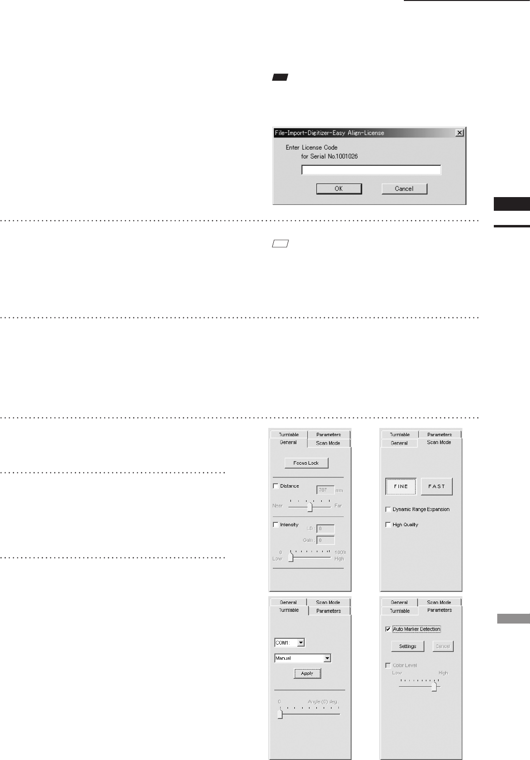
4
Click the [Scan Mode] tab, and set the
scan mode to either Fine or Fast.
5
If you are using a turntable, click the
[Turntable] tab and set the serial port,
the rotating stage type, and the rotation
angle.
6
Set other parameters as necessary.