
Universal Remote User Manual
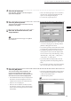
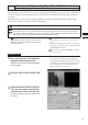
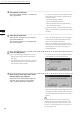
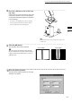
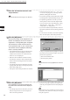
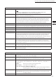
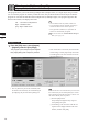
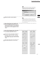
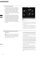
Table Of Contents
- Safety Symbols
- Notes on this Manual
- Trademarks
- About This Manual and Related Documents
- Safety Precautions
- Software Restrictions
- Notes On Use
- Notes On Storage
- Contents
- Conventions for Command Reference (Chapter 2)
- Chapter 1 Forward
- Chapter 2 Command Reference
- File Menu
- File – New
- File – Open
- File – Save – Elements
- File – Save – Scene
- File – Save as – Elements
- File – Save as – Scene
- File – Import – Elements
- File – Import – Digitizer – One Scan
- File – Import – Digitizer – Step Scan
- File – Import – Digitizer – One Scan
- File – Import – Digitizer – Step Scan
- File – Import – Digitizer – PC Card
- File – Import – Digitizer – PC Card
- File – Import – Digitizer – One Scan
- File – Import – Digitizer – Step Scan
- File – Import – Digitizer – PC Card
- File – Import – Digitizer – One Scan
- File – Import – Digitizer – Step Scan
- File – Import – Digitizer – Easy Align
- File – Import – Digitizer – PSC-1
- File – Export – Elements
- File – Export – Images
- File – Remove Elements
- File – Preferences
- File – Select Digitizer
- File – Exit
- View Menu
- Select Menu
- Edit Menu
- Build Menu
- Build – Registration – Initial – Manual
- Build – Registration – Initial – Auto
- Build – Registration – Fine – Elements
- Build – Registration – Fine – Points
- Build – Move – Points
- Build – Move – Elements
- Build – Move – To Origin
- Build – Move – To X-Y-Z
- Build – Rotate – Elements
- Build – Merge
- Build – Fill Holes – Manual
- Build – Fill Holes – Auto
- Build – Smooth – Element
- Build – Smooth – Points
- Build – Subsample – Uniformly – Element
- Build – Subsample – Uniformly – Points
- Build – Subsample – Adaptively – Element
- Build – Subsample – Adaptively – Points
- Build – Modify – Element
- Build – Modify – Points
- Build – Subdivision – Element
- Build – Subdivision – Points
- Build – Triangulate – Elements
- Build – Triangulate – Polygons
- Build – Texture Blending
- Build – Check Polygons – Element
- Build – Check Polygons – Polygons
- Info Menu
- Window Menu
- Tool Menu
- Pop-up Menus in Element View Window
- View Mode – Front/Right/Left/Back/Top/Bottom/Isometric/Perspective
- Rendering Mode – Wireframe/Shading/Texture Mapping/Wireframe+ Shading/Wireframe + Texture Mapping
- Show Vertex/Hide Vertex
- Show Normal/Hide Normal
- Show Axis/Hide Axis
- Smooth Shading/Flat Shading
- Select element from window
- Create clone window
- Close window
- Property
- Pop-up Menus in Element List
- Pop-up Menus in Image Window
- File Menu
- Chapter 3 Appendix
122
Chapter
2
File
Menu
300
File – Import – Digitizer – Step Scan (When VIVID 300 is Selected)
5
Click the [Scan] button.
Scan will start, and both color and range im-
ages will be displayed.
The “Next shot? (angle:**)” message dialog
box will also appear.
4
Set optional parameters.
Check the [Option] checkbox, and make nec-
essary parameters.
• To set the scan reference position (Distance) and
laser intensity (Laser Intensity), perform the fol-
lowing procedure.
q Check the [Option] checkbox.
w Check the [Manual] checkbox.
e Move the [Distance] bar or [Laser Intensity]
bar to the desired position.
• If you are not going to scan both color and range
images at the same time, uncheck the [Auto read]
checkbox.
• If the color and range images are not scanned at
the same time, clicking the [Read] button will
capture a color image and display it.
• If the type of rotating stage has not been desig-
nated, turn the rotating stage manually to the next
angle displayed in the “Next shot? (angle:**)”
message dialog box.
6
Click the [OK] button.
The next specied angle will appear in [Current
Angle], and the object will be scanned for the
next image.
• If a rotating stage has been selected by the Turn-
table, the stage will turn to the next angle and
then the object will be scanned.
• To cancel scan, click the [Cancel] button instead
of the [OK] button, and repeat steps 4 to 5.
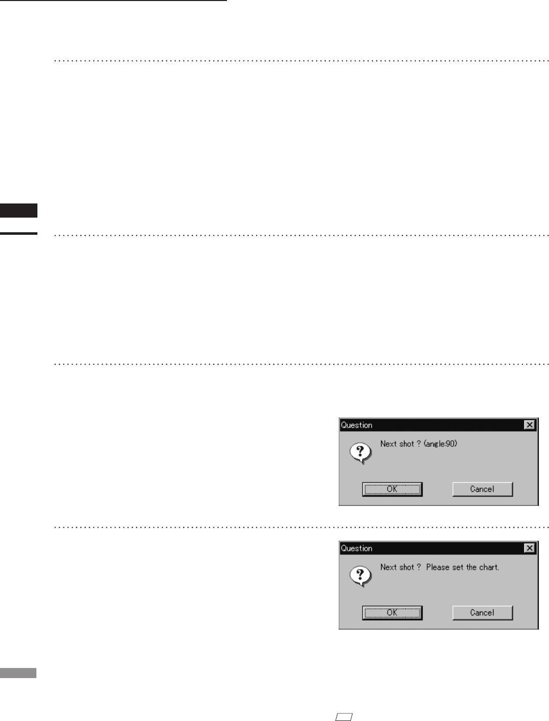
7
Repeat step 6 until shots from all the
desired angles are captured.
When shots from all the desired angles are
captured, the “Next shot? Please set the
chart.” message dialog box will appear.
• If you want to acquire a shot from a certain angle
again, click the angle currently displayed in [Cur-
rent Angle] with the left mouse button, then select
the desired angle from the pull-down menu that
appears.
M
emo
If an angle (rotation step) has been selected at step 3,
necessary steps (angles) to complete 360 degrees will
be displayed in the pull-down menu. However, it is not
necessary to scan at all the angles. You can select neces-
sary steps (angles) only.