
Universal Remote User Manual
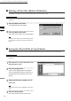
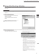
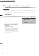
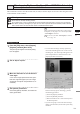
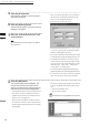
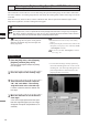
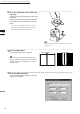
Table Of Contents
- Safety Symbols
- Notes on this Manual
- Trademarks
- About This Manual and Related Documents
- Safety Precautions
- Software Restrictions
- Notes On Use
- Notes On Storage
- Contents
- Conventions for Command Reference (Chapter 2)
- Chapter 1 Forward
- Chapter 2 Command Reference
- File Menu
- File – New
- File – Open
- File – Save – Elements
- File – Save – Scene
- File – Save as – Elements
- File – Save as – Scene
- File – Import – Elements
- File – Import – Digitizer – One Scan
- File – Import – Digitizer – Step Scan
- File – Import – Digitizer – One Scan
- File – Import – Digitizer – Step Scan
- File – Import – Digitizer – PC Card
- File – Import – Digitizer – PC Card
- File – Import – Digitizer – One Scan
- File – Import – Digitizer – Step Scan
- File – Import – Digitizer – PC Card
- File – Import – Digitizer – One Scan
- File – Import – Digitizer – Step Scan
- File – Import – Digitizer – Easy Align
- File – Import – Digitizer – PSC-1
- File – Export – Elements
- File – Export – Images
- File – Remove Elements
- File – Preferences
- File – Select Digitizer
- File – Exit
- View Menu
- Select Menu
- Edit Menu
- Build Menu
- Build – Registration – Initial – Manual
- Build – Registration – Initial – Auto
- Build – Registration – Fine – Elements
- Build – Registration – Fine – Points
- Build – Move – Points
- Build – Move – Elements
- Build – Move – To Origin
- Build – Move – To X-Y-Z
- Build – Rotate – Elements
- Build – Merge
- Build – Fill Holes – Manual
- Build – Fill Holes – Auto
- Build – Smooth – Element
- Build – Smooth – Points
- Build – Subsample – Uniformly – Element
- Build – Subsample – Uniformly – Points
- Build – Subsample – Adaptively – Element
- Build – Subsample – Adaptively – Points
- Build – Modify – Element
- Build – Modify – Points
- Build – Subdivision – Element
- Build – Subdivision – Points
- Build – Triangulate – Elements
- Build – Triangulate – Polygons
- Build – Texture Blending
- Build – Check Polygons – Element
- Build – Check Polygons – Polygons
- Info Menu
- Window Menu
- Tool Menu
- Pop-up Menus in Element View Window
- View Mode – Front/Right/Left/Back/Top/Bottom/Isometric/Perspective
- Rendering Mode – Wireframe/Shading/Texture Mapping/Wireframe+ Shading/Wireframe + Texture Mapping
- Show Vertex/Hide Vertex
- Show Normal/Hide Normal
- Show Axis/Hide Axis
- Smooth Shading/Flat Shading
- Select element from window
- Create clone window
- Close window
- Property
- Pop-up Menus in Element List
- Pop-up Menus in Image Window
- File Menu
- Chapter 3 Appendix
106
Chapter
2
File
Menu
700
File – Import – Digitizer – Step Scan (When VIVID 700 is Selected)
Performing Step Scan with the VIVID 700
This command is used to take two or more shots using the optional rotating stage via the remote control func-
tion of this software. If a rotating stage has been selected by the rotating table, rotation of the stage can also be
controlled.
After the necessary shots are taken, scan the calibration chart. Data acquired from different angles will be
subjected to registration, and the resulting data will appear.
Warning
Never stare into the laser emitting window.
Do not place a lens, mirror or optical element in the passage of the laser beam. Doing so may converge the
laser beam, resulting in damage to your eyes, burns or re. To prevent the above accidents, make sure that a
wall or similar which can block the laser beam is located behind the object.
Note
Iftherotatingstagedoesnotoperatecorrectlyfromthe
dialogbox,turnOFFthestage,turnitONagain,and
thentrytooperateit.
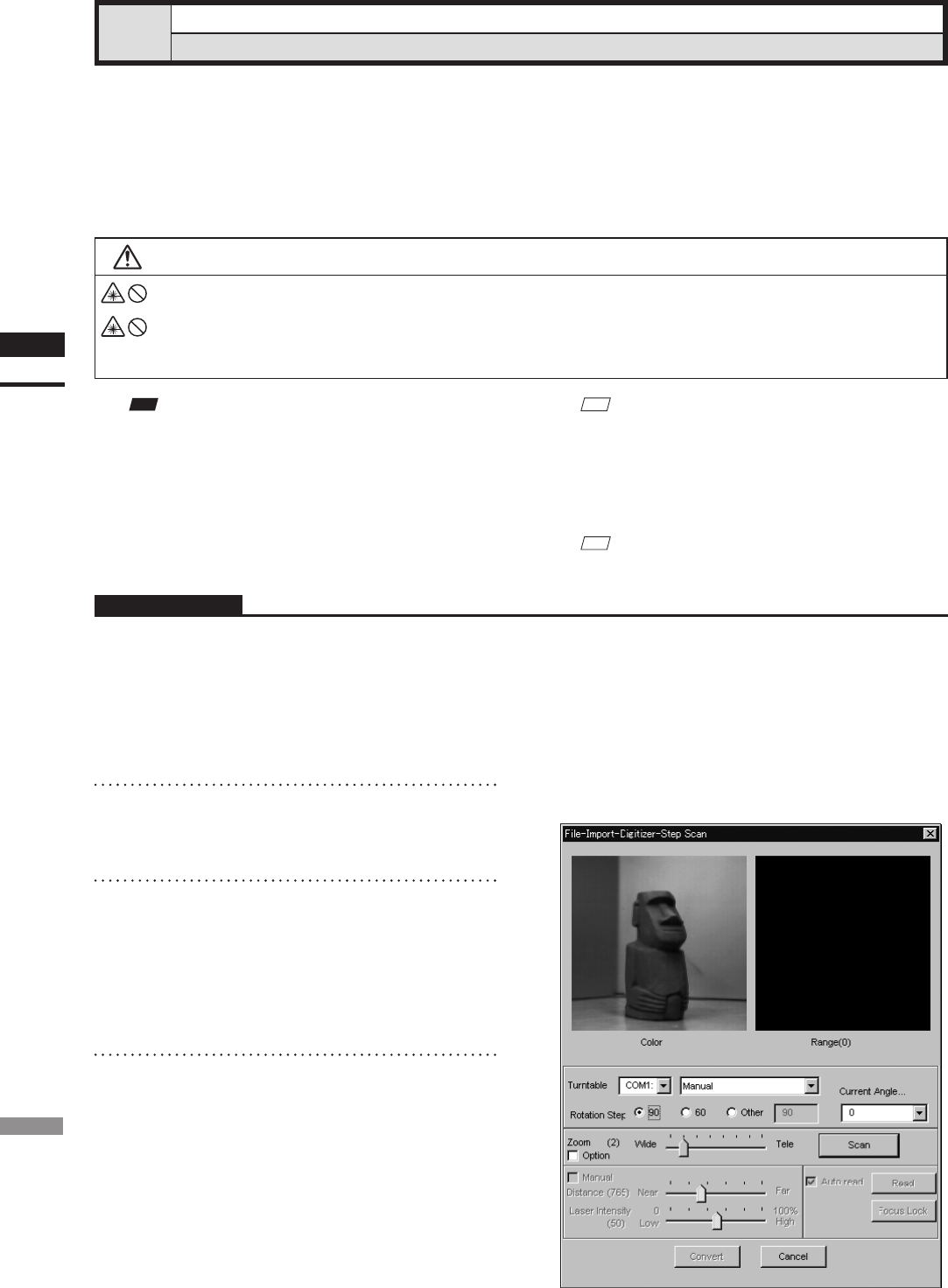
Operating Procedure
1
From the [File] menu, select [Import],
[Digitizer] and then [Step Scan].
The [File-Import-Digitizer-Step Scan] dialog
box will appear.
M
emo
• The calibration chart is an accessory of the rotating
stage set.
• Before performing the procedure below, make sure that
the digitizer you are going to use is selected by the File
– Select Digitizer command.
Ref.
For details of the File–SelectDigitizercommand,
refer to page 144.
2
Place the object on the rotating stage.
3
Select the desired rotation step from
“90”, “60” and “Other”. The rotating
stage will rotate at the selected step.
If “Other” is selected, enter the desired rota-
tion angle.
4
Move the Zoom bar to set the desired
view angle.
A new color image captured from the speci-
ed view angle will appear. (No color image
will appear if the [Auto read] checkbox is un-
checked.)
• The color monitor image currently captured by
the VIVID 700 will appear in the “Color” area of
the dialog box. (No color image will appear if the
[Auto read] checkbox is unchecked even if the
[Option] checkbox is checked.)