
Universal Remote User Manual

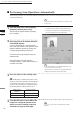
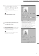
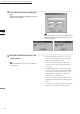
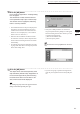
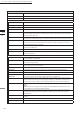
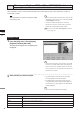
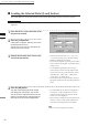
Table Of Contents
- Safety Symbols
- Notes on this Manual
- Trademarks
- About This Manual and Related Documents
- Safety Precautions
- Software Restrictions
- Notes On Use
- Notes On Storage
- Contents
- Conventions for Command Reference (Chapter 2)
- Chapter 1 Forward
- Chapter 2 Command Reference
- File Menu
- File – New
- File – Open
- File – Save – Elements
- File – Save – Scene
- File – Save as – Elements
- File – Save as – Scene
- File – Import – Elements
- File – Import – Digitizer – One Scan
- File – Import – Digitizer – Step Scan
- File – Import – Digitizer – One Scan
- File – Import – Digitizer – Step Scan
- File – Import – Digitizer – PC Card
- File – Import – Digitizer – PC Card
- File – Import – Digitizer – One Scan
- File – Import – Digitizer – Step Scan
- File – Import – Digitizer – PC Card
- File – Import – Digitizer – One Scan
- File – Import – Digitizer – Step Scan
- File – Import – Digitizer – Easy Align
- File – Import – Digitizer – PSC-1
- File – Export – Elements
- File – Export – Images
- File – Remove Elements
- File – Preferences
- File – Select Digitizer
- File – Exit
- View Menu
- Select Menu
- Edit Menu
- Build Menu
- Build – Registration – Initial – Manual
- Build – Registration – Initial – Auto
- Build – Registration – Fine – Elements
- Build – Registration – Fine – Points
- Build – Move – Points
- Build – Move – Elements
- Build – Move – To Origin
- Build – Move – To X-Y-Z
- Build – Rotate – Elements
- Build – Merge
- Build – Fill Holes – Manual
- Build – Fill Holes – Auto
- Build – Smooth – Element
- Build – Smooth – Points
- Build – Subsample – Uniformly – Element
- Build – Subsample – Uniformly – Points
- Build – Subsample – Adaptively – Element
- Build – Subsample – Adaptively – Points
- Build – Modify – Element
- Build – Modify – Points
- Build – Subdivision – Element
- Build – Subdivision – Points
- Build – Triangulate – Elements
- Build – Triangulate – Polygons
- Build – Texture Blending
- Build – Check Polygons – Element
- Build – Check Polygons – Polygons
- Info Menu
- Window Menu
- Tool Menu
- Pop-up Menus in Element View Window
- View Mode – Front/Right/Left/Back/Top/Bottom/Isometric/Perspective
- Rendering Mode – Wireframe/Shading/Texture Mapping/Wireframe+ Shading/Wireframe + Texture Mapping
- Show Vertex/Hide Vertex
- Show Normal/Hide Normal
- Show Axis/Hide Axis
- Smooth Shading/Flat Shading
- Select element from window
- Create clone window
- Close window
- Property
- Pop-up Menus in Element List
- Pop-up Menus in Image Window
- File Menu
- Chapter 3 Appendix
98
Chapter
2
File
Menu
900
910
File – Import – Digitizer – PC Card (When VIVID 900/910 is Selected)
n Loading the Selected Data ([Load] button)
The [Load] button is used to load the data of the selected le from the memory card to the software.
Operating Procedure
Before starting the following procedure, make sure that the [File-Import-Digitizer-PC Card] dialog box is
displayed.
1
From the file list, select the name of the
file you want to load.
2
Click the [Load] button.
A dialog box will appear, allowing you to enter
the desired element name.
The le name in the memory card will be dis-
played as an element name.
3
Change the element name if necessary,
and set the parameters.
• Select the desired rate from “1/1”, “1/4”, “1/9”,
“1/16” and “No polygon” by selecting from the
[Reduction Rate] pull-down menu.
• If you want to program to generate points to ll in
holes caused by missing data, set the [File Holes]
setting to “On”.
• Use the [Remove] pull-down menu to select
which points to remove from the imported data.
You can set this to any of the following: “None”,
“Boundary(B.)”, “5deg. & B.”, “10deg. & B.”,
“15deg. & B.”, or “20deg. & B.”
• If you want to lter the imported data, select the
appropriate parameter from the [Filter] pull-down
menu.
4
Click the [OK] button.
The data of the selected le will be loaded
and displayed in the element view window.
The names of the imported elements will also
appear in the element list, indicating that the
elements have been selected (highlighted).
• The loaded data will be ready to be displayed in
all windows. It will be displayed in the active
window and the windows for which all the ele-
ments are set to be displayed.
• When the data is loaded for the rst time after the
software is started, it will be fully framed in all
the windows including those that are hidden.
M
emo
A clock icon will be displayed during loading.