
Universal Remote User Manual
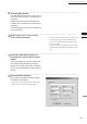
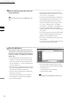
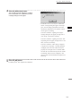
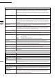
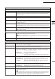

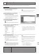
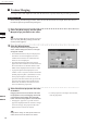
Table Of Contents
- Safety Symbols
- Notes on this Manual
- Trademarks
- About This Manual and Related Documents
- Safety Precautions
- Software Restrictions
- Notes On Use
- Notes On Storage
- Contents
- Conventions for Command Reference (Chapter 2)
- Chapter 1 Forward
- Chapter 2 Command Reference
- File Menu
- File – New
- File – Open
- File – Save – Elements
- File – Save – Scene
- File – Save as – Elements
- File – Save as – Scene
- File – Import – Elements
- File – Import – Digitizer – One Scan
- File – Import – Digitizer – Step Scan
- File – Import – Digitizer – One Scan
- File – Import – Digitizer – Step Scan
- File – Import – Digitizer – PC Card
- File – Import – Digitizer – PC Card
- File – Import – Digitizer – One Scan
- File – Import – Digitizer – Step Scan
- File – Import – Digitizer – PC Card
- File – Import – Digitizer – One Scan
- File – Import – Digitizer – Step Scan
- File – Import – Digitizer – Easy Align
- File – Import – Digitizer – PSC-1
- File – Export – Elements
- File – Export – Images
- File – Remove Elements
- File – Preferences
- File – Select Digitizer
- File – Exit
- View Menu
- Select Menu
- Edit Menu
- Build Menu
- Build – Registration – Initial – Manual
- Build – Registration – Initial – Auto
- Build – Registration – Fine – Elements
- Build – Registration – Fine – Points
- Build – Move – Points
- Build – Move – Elements
- Build – Move – To Origin
- Build – Move – To X-Y-Z
- Build – Rotate – Elements
- Build – Merge
- Build – Fill Holes – Manual
- Build – Fill Holes – Auto
- Build – Smooth – Element
- Build – Smooth – Points
- Build – Subsample – Uniformly – Element
- Build – Subsample – Uniformly – Points
- Build – Subsample – Adaptively – Element
- Build – Subsample – Adaptively – Points
- Build – Modify – Element
- Build – Modify – Points
- Build – Subdivision – Element
- Build – Subdivision – Points
- Build – Triangulate – Elements
- Build – Triangulate – Polygons
- Build – Texture Blending
- Build – Check Polygons – Element
- Build – Check Polygons – Polygons
- Info Menu
- Window Menu
- Tool Menu
- Pop-up Menus in Element View Window
- View Mode – Front/Right/Left/Back/Top/Bottom/Isometric/Perspective
- Rendering Mode – Wireframe/Shading/Texture Mapping/Wireframe+ Shading/Wireframe + Texture Mapping
- Show Vertex/Hide Vertex
- Show Normal/Hide Normal
- Show Axis/Hide Axis
- Smooth Shading/Flat Shading
- Select element from window
- Create clone window
- Close window
- Property
- Pop-up Menus in Element List
- Pop-up Menus in Image Window
- File Menu
- Chapter 3 Appendix
130
Chapter
2
File
Menu
910
File – Import – Digitizer – Easy Align
1
3
Enter an element name and set the ele-
ment parameters.
14
Click the [OK] button.
The temporary window (the window that was
showing the pre-converted image) closes. The
program converts the data that was displayed
in the store window, and displays the resulting
aligned data.
• The loaded data will be ready for display in all
windows. It will be shown in the active window
and in those windows for which all elements are
set to be displayed (i.e., in those windows that are
not set to “Selective”).
• The rst time the program loads data after starting
up, it will be fully framed in all windows (includ-
ing those that are hidden automatically).
• If you are using the rotating stage, the stage now
rotates back to its origin.
• For elements that existed prior to execution of
this command, the selection status and display
states remain unchanged.
• Select the data resolution from the [Reduction
Rate] pull-down menu. Choices are: “1/1”, “1/4”,
“1/9”, “1/16”, or “No polygon”.
• If you want the program to ll-in lost data areas
when loading the data, set [Fill Holes] to “On”.
• At the [Remove] pull-down menu, select the
data to be excluded at time of loading. Choices
are: “None”, “Boundary (B.)”, “5deg.& B.”,
“10deg.& B.”, “15deg.& B.”, and “20deg.& B.”
• If you want to lter the data when loading it,
make the appropriate selection at the [Filter] pull-
down menu.
• If you want to apply 3D processing to the marker
sections, make the appropriate selection at the
[Marker Correction] pull-down menu.
• If you want to use texturing, check the [Use Tex-
ture] checkbox.
• If you want to save the data at the time of conver-
sion, check the [Save Data] checkbox.
Note
Enteranelementnameofupto31alphanumericchar-
acters.
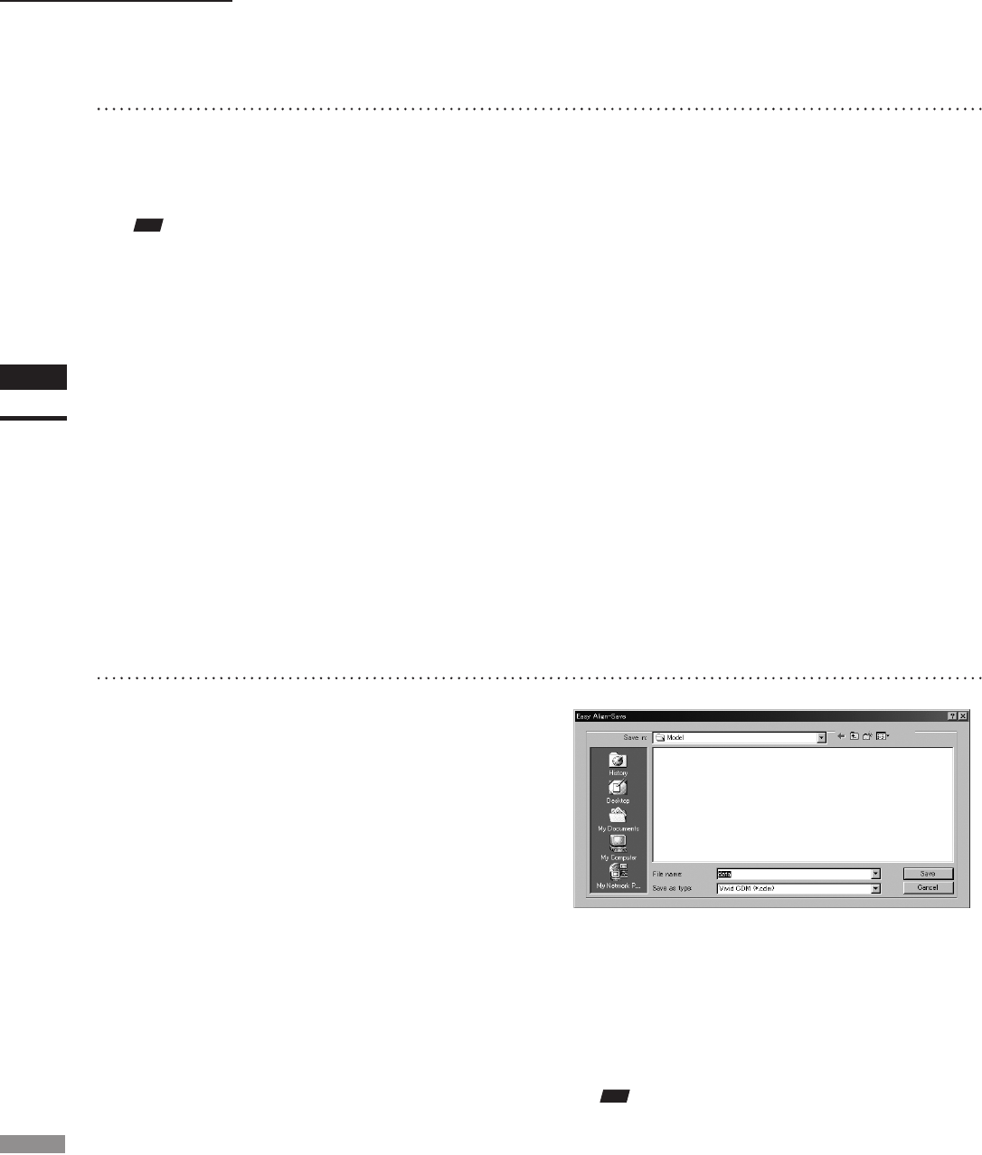
• If you checked [Save Data] (at Step 13 above),
the program opens the [Easy Align-Save] dialog
box (shown above).
q Enter a lename for the saved le.
w Click the [Save] button.
Note
Thelenamemustbealphanumericcharactersonly.