
Universal Remote User Manual
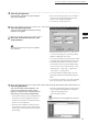
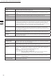
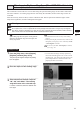
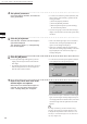
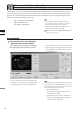
Table Of Contents
- Safety Symbols
- Notes on this Manual
- Trademarks
- About This Manual and Related Documents
- Safety Precautions
- Software Restrictions
- Notes On Use
- Notes On Storage
- Contents
- Conventions for Command Reference (Chapter 2)
- Chapter 1 Forward
- Chapter 2 Command Reference
- File Menu
- File – New
- File – Open
- File – Save – Elements
- File – Save – Scene
- File – Save as – Elements
- File – Save as – Scene
- File – Import – Elements
- File – Import – Digitizer – One Scan
- File – Import – Digitizer – Step Scan
- File – Import – Digitizer – One Scan
- File – Import – Digitizer – Step Scan
- File – Import – Digitizer – PC Card
- File – Import – Digitizer – PC Card
- File – Import – Digitizer – One Scan
- File – Import – Digitizer – Step Scan
- File – Import – Digitizer – PC Card
- File – Import – Digitizer – One Scan
- File – Import – Digitizer – Step Scan
- File – Import – Digitizer – Easy Align
- File – Import – Digitizer – PSC-1
- File – Export – Elements
- File – Export – Images
- File – Remove Elements
- File – Preferences
- File – Select Digitizer
- File – Exit
- View Menu
- Select Menu
- Edit Menu
- Build Menu
- Build – Registration – Initial – Manual
- Build – Registration – Initial – Auto
- Build – Registration – Fine – Elements
- Build – Registration – Fine – Points
- Build – Move – Points
- Build – Move – Elements
- Build – Move – To Origin
- Build – Move – To X-Y-Z
- Build – Rotate – Elements
- Build – Merge
- Build – Fill Holes – Manual
- Build – Fill Holes – Auto
- Build – Smooth – Element
- Build – Smooth – Points
- Build – Subsample – Uniformly – Element
- Build – Subsample – Uniformly – Points
- Build – Subsample – Adaptively – Element
- Build – Subsample – Adaptively – Points
- Build – Modify – Element
- Build – Modify – Points
- Build – Subdivision – Element
- Build – Subdivision – Points
- Build – Triangulate – Elements
- Build – Triangulate – Polygons
- Build – Texture Blending
- Build – Check Polygons – Element
- Build – Check Polygons – Polygons
- Info Menu
- Window Menu
- Tool Menu
- Pop-up Menus in Element View Window
- View Mode – Front/Right/Left/Back/Top/Bottom/Isometric/Perspective
- Rendering Mode – Wireframe/Shading/Texture Mapping/Wireframe+ Shading/Wireframe + Texture Mapping
- Show Vertex/Hide Vertex
- Show Normal/Hide Normal
- Show Axis/Hide Axis
- Smooth Shading/Flat Shading
- Select element from window
- Create clone window
- Close window
- Property
- Pop-up Menus in Element List
- Pop-up Menus in Image Window
- File Menu
- Chapter 3 Appendix
119
Chapter
2
File
Menu
300
File – Import – Digitizer – One Scan (When VIVID 300 is Selected)
5
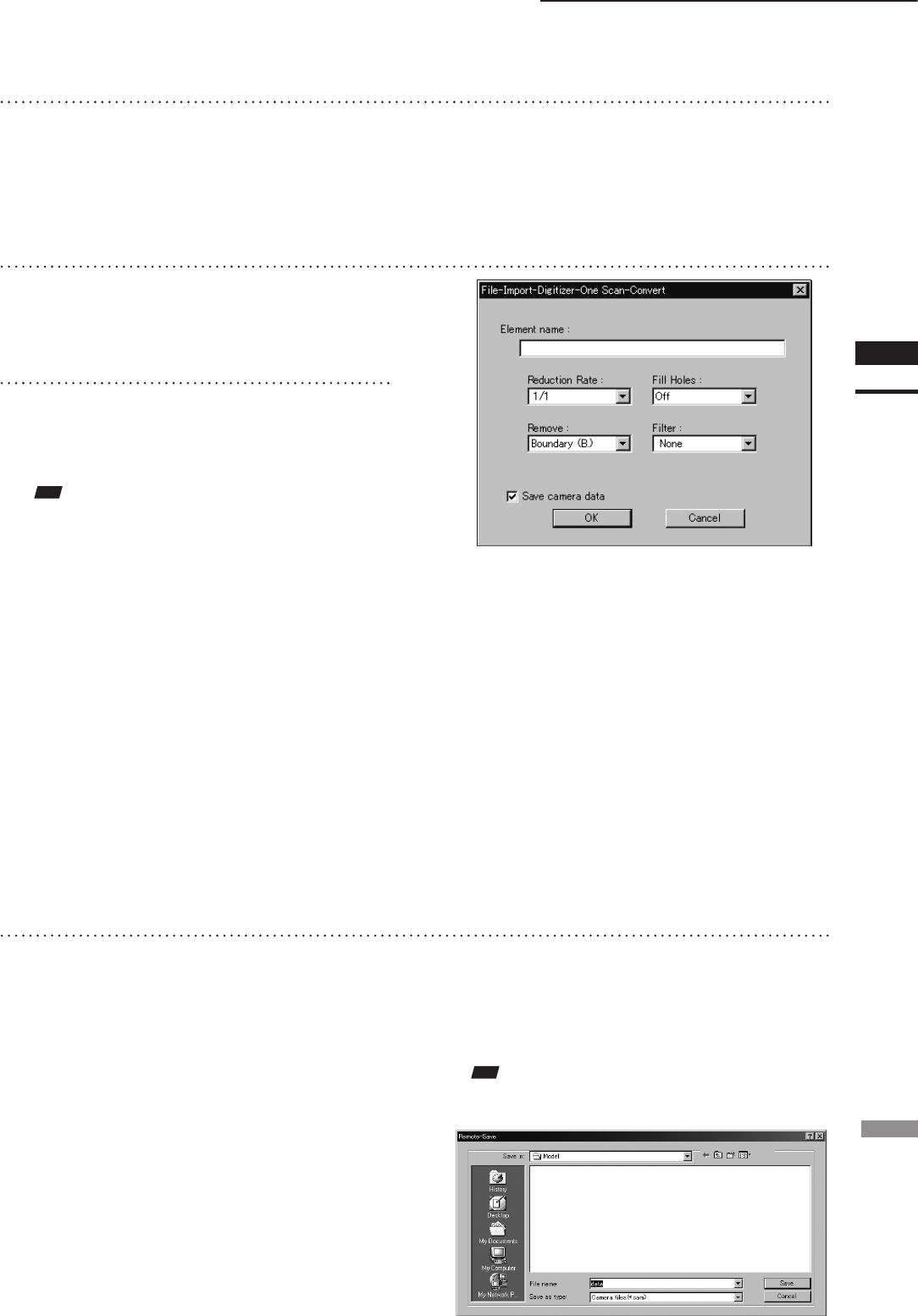
Click the [Convert] button.
The [File-Import-Digitizer-One Scan-Convert]
dialog box will appear.
6
Enter the desired element name, and
set parameters.
4
Click the [Scan] button.
Scan will start, and both color and range im-
ages will be displayed.
• If the color and range images are not scanned at
the same time, clicking the [Read] button will
capture a color image and display it.
• To restart scan, repeat steps 2 to 3.
• Select the desired rate from “1/1”, “1/4”, “1/9”,
“1/16” and “No polygon” by selecting from the
[Reduction Rate] pull-down menu.
• If you want to generate points to ll in holes caused
by missing data, set the [File Holes] setting to “On”.
• The [Remove] pull-down menu lets you select
which points to remove from the imported data.
You can set this to any of the following: “None”,
“Boundary(B.)”, “5deg. & B.”, “10deg. & B.”,
“15deg. & B.”, or “20deg. & B.”
• If you want to lter the imported data, select the
appropriate parameter from the [Filter] pull-down
menu.
• To save the raw scan data (.cam) when importing
data, check the [Save camera data] checkbox.
Note
Theelementnamemustconsistofupto31alphanu-
mericcharacters.
7
Click the [OK] button.
The scanned image will be displayed. The
names of the imported elements will also
appear in the element list, indicating that the
elements have been selected (highlighted).
• The loaded data will be ready to be displayed in
all windows. It will be displayed in the active
window and the windows for which all the ele-
ments are set to be displayed.
• When the data is loaded for the rst time after
the software is started, it will be fully framed in
all the windows including those that are hidden
automatically.
• If the [Save camera data] checkbox was checked at
step 7, the [Remote-Save] dialog box will appear.
q Enter the desired le name.
w Click the [Save] button.
Note
Thelenamemustconsistofalphanumericcharacters
only.