
Installation Guide

12 TT-1596 3/15
PIM
LCM or
load shed
kit
RXT
4
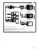
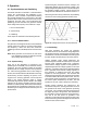
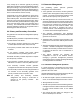
Note: See Figure 15 for maximum total cable length.
COM
PWR
A
B
3
5
6
COM
PWR
A
B
COM
PWR
A
B
6
1
2
GND
APM PIB
DIODE BOARD
1. Factory connection, diode board to APM PIB.
2. Customer connections, generator 1 and generator 2 RDC2 controllers to APM diode board
3. Connect one end of each cable shield to GROUND.
4. Communication cable Belden #9402 or equivalent 20 AWG shielded, twisted-pair cable
5. Connect shields together.
6. Leave one end of each cable shield disconnected at the last device.
Figure 16 Communication (RBUS) Connection Details