SERVICE MANUAL COMMAND CH18-745 HORIZONTAL CRANKSHAFT
Section 1 Safety and General Information CH18-745 1 Section 1 Safety and General Information Safety Precautions To ensure safe operation please read the following statements and understand their meaning. Also refer to your equipment manufacturer's manual for other important safety information. This manual contains safety precautions which are explained below. Please read carefully.
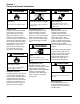
Section 1 Safety and General Information WARNING WARNING WARNING Explosive Fuel can cause fires and severe burns. Carbon Monoxide can cause severe nausea, fainting or death. Explosive Gas can cause fires and severe acid burns. Stop engine before filling fuel tank. Do not operate engine in closed or confined area. Charge battery only in a well ventilated area. Keep sources of ignition away. Explosive Fuel! Gasoline is extremely flammable and its vapors can explode if ignited.
Section 1 Safety and General Information Engine Identification Numbers When ordering parts, or in any communication involving an engine, always give the Model, Specification and Serial Numbers, including letter suffixes if there are any. 1 The engine identification numbers appear on a decal, or decals, affixed to the engine shrouding. See Figure 1-1. An explanation of these numbers is shown in Figure 1-2. Identification Decal Figure 1-1. Engine Identification Decal Location. A. Model No.
Section 1 Safety and General Information Oil Recommendations Using the proper type and weight of oil in the crankcase is extremely important. So is checking oil daily and changing oil regularly. Failure to use the correct oil, or using dirty oil, causes premature engine wear and failure. Oil Type Use high-quality detergent oil of API (American Petroleum Institute) Service Class SG, SH, SJ or higher. Select the viscosity based on the air temperature at the time of operation as shown in the following table.
Section 1 Safety and General Information Periodic Maintenance Instructions WARNING: Accidental Starts! Disabling engine. Accidental starting can cause severe injury or death. Before working on the engine or equipment, disable the engine as follows: 1) Disconnect the spark plug lead(s). 2) Disconnect negative (-) battery cable from battery. Maintenance Schedule These required maintenance procedures should be performed at the frequency stated in the table.
Section 1 Safety and General Information Dimensions in millimeters. Inch equivalents shown in (). Figure 1-4. Typical Engine Dimensions CH Series with Standard Flat Air Cleaner. 1.
Section 1 Safety and General Information Dimensions in millimeters. Inch equivalents shown in (). 1 Figure 1-5. Typical Engine Dimensions CH EFI Series with Heavy-Duty Air Cleaner. 1.
Section 1 Safety and General Information General Specifications¹ Power (@ 3600 RPM, corrected to SAE J1995) CH18 ............................................................................................................................ 13.4 kW (18 HP) CH20 ............................................................................................................................ 14.9 kW (20 HP) CH22/23 ........................................................................................................
Section 1 Safety and General Information Camshaft End Play (With Shim) .................................................................................. 0.076/0.127 mm (0.0030/0.0050 in.) 1 Running Clearance ...................................................................................... 0.025/0.063 mm (0.0010/0.0025 in.) Bore I.D. New ....................................................................................................... 20.000/20.025 mm (0.7874/0.7884 in.) Max. Wear Limit ........
Section 1 Safety and General Information Closure Plate Closure Plate Fastener Torque .............................................................. 24.4 N·m (216 in. lb.) Crankshaft End Play (Free) .................................................................................... 0.070/0.590 mm (0.0028/0.0230 in.) End Play (With Thrust Bearing Components) ....................................... 0.070/0.270 mm (0.0028/0.0100 in.) Except CH25 Engines Below Serial No. 2403500008 .................... 0.050/0.
Section 1 Safety and General Information Cylinder Head Cylinder Head Fastener Torque Hex. Flange Nut - Torque in Two Stages .......................................... initially to 16.9 N·m (150 in. lb.) finally to 33.9 N·m (300 in. lb.) 1 Head Bolt - Torque in Two Stages .................................................. initially to 22.6 N·m (200 in. lb.) finally to 41.8 N·m (370 in. lb.) Max. Out-of-Flatness ............................................................................ 0.076 mm (0.003 in.
Section 1 Safety and General Information Muffler Muffler Retaining Nut Torque .................................................................. 24.4 N·m (216 in. lb.) Oil Filter Oil Filter Torque .................................................................................... 10.4-12.7 N·m (90-110 in. lb.) Oil Cooler Oil Cooler/Adapter Nipple Torque ......................................................... 27 N·m (20 ft. lb.) Piston, Piston Rings, and Piston Pin Piston-to-Piston Pin Running Clearance .
Section 1 Safety and General Information Piston, Piston Rings, and Piston Pin cont. Piston Thrust Face-to-Cylinder Bore² Running Clearance New - CH18, CH20, CH22 (624 cc) ............................................... 0.014/0.057 mm (0.0005/0.0022 in.) New - CH22/23 (674 cc) ................................................................. 0.021/0.062 mm (0.0008/0.0024 in.) New - CH25, CH26, CH730-745 .................................................... 0.001/0.045 mm (0.039/0.0018 in.
Section 1 Safety and General Information Valves and Valve Lifters cont. Exhaust Valve Guide I.D. New ................................................................................................ 7.038/7.058 mm (0.2771/0.2779 in.) Max. Wear Limit ............................................................................. 7.159 mm (0.2819 in.) Valve Guide Reamer Size Standard ......................................................................................... 7.048 mm (0.2775 in.) 0.25 mm O.S. .....
Section 1 Safety and General Information English Fastener Torque Recommendations for Standard Applications 1 Tightening Torque: N·m (in. lb.) + or - 20% Bolts, Screws, Nuts and Fasteners Assembled Into Cast Iron or Steel Size 8-32 10-24 10-32 1/4-20 1/4-28 5/16-18 5/16-24 3/8-16 3/8-24 Grade 2 or 5 Fasteners Into Aluminum Grade 2 Grade 5 Grade 8 2.3 (20) 3.6 (32) 3.6 (32) 7.9 (70) 9.6 (85) 17.0 (150) 18.7 (165) 29.4 (260) 33.9 (300) 2.8 (25) 4.5 (40) 4.5 (40) 13.0 (115) 15.8 (140) 28.3 (250) 30.
Section 1 Safety and General Information 1.
Section 2 Special Tools CH18-745 Section 2 Special Tools 2 Certain quality tools are designed to help you perform specific disassembly, repair, and reassembly procedures. By using tools designed for the job, you can service engines easier, faster, and safer! In addition, you’ll increase your service capabilities and customer satisfaction by decreasing engine downtime. Kohler special tools are handled by SPX Corp., a division of Owatonna Tool Corp. (OTC).
Section 2 Special Tools Find a used connecting rod from a 10 HP or larger engine. Remove and discard the rod cap. If it is a PosiLock rod, you will also need to remove the studs. If it is a Command rod, you will need to grind off the aligning steps, so the joint surface is flat. Find a 1 in. long capscrew with the correct thread size to match the threads in the connecting rod. Obtain a flat washer with the correct I.D. to slip on the capscrew and an O.D. of approximately 1 in. Kohler Part No.
Section 2 Special Tools RTV Silicone Sealant RTV silicone sealant is used as a gasket between the crankcase and closure plate. Only oxime-based, oil resistant RTV sealants, such as those listed below, are approved for use. Loctite® Nos. 5900 and 5910 are recommended for best sealing characteristics. Loctite® Ultra Blue 587 Loctite® Ultra Copper Loctite® Ultra Black 598 Loctite® 5900 (Heavy Body) Loctite® 5910 NOTE: Always use fresh sealant. Using outdated sealant can result in leakage.
Section 2 Special Tools 2.
Section 3 Troubleshooting CH18-745 Section 3 Troubleshooting Troubleshooting Guide When troubles occur, be sure to check the simple causes which, at first, may seem too obvious to be considered. For example, a starting problem could be caused by an empty fuel tank. Some general common causes of engine troubles are listed below. Use these to locate the causing factors. Refer to the specific section(s) within this service manual for more detailed information. Engine Cranks But Will Not Start 1.
Section 3 Troubleshooting Engine Will Not Idle 1. Dirt or water in the fuel system. 2. Stale fuel and/or gum in carburetor. 3. Faulty spark plugs. 4. Fuel supply inadequate. 5. Idle speed adjusting screw improperly set. 6. Idle fuel adjusting needle improperly set (some models). 7. Low compression. 8. Restricted fuel tank cap vent. 9. Engine overheated-cooling system/air circulation problem. Engine Overheats 1. Air intake/grass screen, cooling fins, or cooling shrouds clogged. 2. Excessive engine load. 3.
Section 3 Troubleshooting • Check the condition of the oil. Drain the oil into a container - the oil should flow freely. Check for metal chips and other foreign particles. Sludge is a natural by-product of combustion; a small accumulation is normal. Excessive sludge formation could indicate overrich carburetion, weak ignition, overextended oil change interval or wrong weight or type of oil was used, to name a few. NOTE: It is good practice to drain oil at a location away from the workbench.
Section 3 Troubleshooting No Crankcase Vacuum/Pressure in Crankcase Possible Cause Solution 1. Crankcase breather clogged or inoperative. 1. Disassemble breather, clean parts thoroughly, check sealing surfaces for flatness, reassemble, and recheck pressure. 2. Seals and/or gaskets leaking. Loose or improperly torqued fasteners. 2. Replace all worn or damaged seals and gaskets. Make sure all fasteners are tightened securely. Use appropriate torque values and sequences when necessary. 3.
Section 3 Troubleshooting Leakdown Test Results Air escaping from crankcase breather ................................................... Defective rings or worn cylinder. Air escaping from exhaust system ......................................................... Defective exhaust valve. Air escaping from carburetor ................................................................. Defective intake valve. Gauge reading in “low” (green) zone .....................................................
Section 3 Troubleshooting 3.
Section 4 CH18-745 Air Cleaner and Air Intake System Section 4 Air Cleaner and Air Intake System Air Cleaners General Most engines are equipped with a replaceable, highdensity paper air cleaner element, surrounded by an oiled foam precleaner, and housed under a flat outer cover. This is typically referred to as the standard air cleaner assembly. See Figures 4-1 and 4-4. Some engines utilize a heavy-duty style air cleaner as shown in Figure 4-12. 4 Figure 4-2. Removing Latch Style Cover.
Section 4 Air Cleaner and Air Intake System 3. Wash the precleaner in warm water with detergent. Rinse the precleaner thoroughly until all traces of detergent are eliminated. Squeeze out excess water (do not wring). Allow the precleaner to air dry. 4. Saturate the precleaner with new engine oil. Squeeze out all excess oil. Seal 5. Reinstall the precleaner over the paper air cleaner element. 6. Reinstall the air cleaner cover. Secure the cover with the two latches or the retaining knob.
Section 4 Air Cleaner and Air Intake System 5. Check the seal for any damage or deterioration. Replace as necessary. See Figure 4-7. 6. Reinstall the seal, paper element, precleaner, element cover, and wing nut. 7. Reinstall the air cleaner cover and secure with the latches or the retaining knob. NOTE: Make sure the correct depth air cleaner element and rubber seal are used for the engine spec involved. Some engines use a deeper or extra capacity air cleaner and a longer rubber seal. 4 Figure 4-8.
Section 4 Air Cleaner and Air Intake System Air Cleaner Element Cover and Seal - Make sure element cover is not bent or damaged. Make sure the wing nut and seal are in place to ensure the element is sealed against leakage. Air Cleaner Base - Make sure the base is secured tightly to the carburetor and not cracked or damaged. Breather Tube - Make sure the tube is attached to both the air cleaner base and the breather cover. Figure 4-9. Bracket Retaining Screw.
Section 4 Air Cleaner and Air Intake System 4. Do not wash the paper element and inner element or use compressed air, this will damage the elements. Replace dirty, bent or damaged elements with new genuine Kohler elements as required. Handle the new elements carefully; do not use if the sealing surfaces are bent or damaged. 5. Check all parts for wear, cracks, or damage. Replace any damaged components. Figure 4-12. Heavy-Duty Air Cleaner.
Section 4 Air Cleaner and Air Intake System Figure 4-14. Adapters for Heavy-Duty Air Cleaners. Air Intake/Cooling System To ensure proper cooling, make sure the grass screen, cooling fan fins, and external surfaces of the engine are kept clean at all times. Every 100 hours of operation (more often under extremely dusty or dirty conditions), remove the blower housing and other cooling shrouds.*Clean the cooling fins and external surfaces as necessary. Make sure the cooling shrouds are reinstalled.
Section 5 Fuel System and CH18-745 Governor Section 5 Fuel System and Governor Description The Command horizontal twins use three different types of fuel systems; carbureted, electronic fuel injection (EFI), or gaseous. Gaseous fuel systems can be either liquefied petroleum gas (LPG or LP) or natural gas (NG). Some dual-fuel engines have a combination system, which allows the operator to select either gasoline or LP. This section covers the standard carbureted fuel systems.
Section 5 Fuel System and Governor Gasoline/Ether blends Methyl Tertiary Butyl Ether (MTBE) and unleaded gasoline blends (up to a maximum of 15% MTBE by volume) are approved as a fuel for Kohler engines. Other gasoline/ether blends are not approved. Fuel Filter Most engines are equipped with an in-line filter. Visually inspect the filter periodically and replace when dirty with a genuine Kohler filter.
Section 5 Fuel System and Governor Fuel Pump General These engines are equipped with either a pulse or mechanical fuel pump. See Figures 5-1 and 5-2. The pumping action is created by either the oscillation of positive and negative pressures within the crankcase through a hose, or by direct lever/pump actuation off rocker arm movement. The pumping action causes the diaphragm on the inside of the pump to pull fuel in on its downward stroke and to push it into the carburetor on its upward stroke.
Section 5 Fuel System and Governor Carburetor General These engines are equipped with fixed main jet carburetors manufactured by Keihin to Kohler specifications. Most have automatic chokes and fuel shut-off solenoids. Keihin carburetors with accelerator pump features are standard on many models, and are furnished as an option on other CH applications where improved performance is required during periods of rapid acceleration.
Section 5 Fuel System and Governor Troubleshooting Checklist When the engine starts hard, runs roughly or stalls at low idle speed, check the following areas before adjusting or disassembling the carburetor. • Make sure the fuel tank is filled with clean, fresh gasoline. • Make sure the fuel tank cap vent is not blocked and that it is operating properly. • Make sure fuel is reaching the carburetor.
Section 5 Fuel System and Governor Carburetor Adjustments General In compliance with government emission standards, the carburetor is calibrated to deliver the correct air-tofuel mixture to the engine under all operating conditions. The high-speed mixture is preset and cannot be adjusted. Pre-compliance carburetors contain a low idle fuel adjusting needle, on “certified” compliance carburetors, both the low and high speed mixture circuits are pre-established and cannot be adjusted.
Section 5 Fuel System and Governor 2. Disconnect the fuel line from the carburetor. See Figure 5-6. Tab 3. Clean dirt and debris from exterior of carburetor. 4. Remove the four screws holding the two carburetor halves together. Carefully lift the upper body off the carburetor body and disconnect choke linkage. Float Screws Fuel Line Figure 5-7. Carburetor Float Adjustment. 8.
Section 5 Fuel System and Governor 7. In order to clean the ‘‘off-idle’’ vent ports and bowl vent thoroughly, use a good carburetor solvent (like Gumout™). Blow clean compressed air through the idle adjusting needle hole. Be careful to use a suitable shop rag to prevent debris from hitting someone. 8. Remove the preformed rubber gasket only if it is to be replaced. If it is removed for any reason, replace it. Inspection/Repair Carefully inspect all components and replace those that are worn or damaged.
Section 5 Fuel System and Governor 1. 2. 3. 4. 5. 6. 7. 8. 9. 10. 11. 12. 13. 14. 15. 16. 17. 18. 19. 20. 21. 22.
Section 5 Fuel System and Governor Reassembly Governor Spring Reassemble the carburetor using the following steps. See Figure 5-9. Cross Shaft 1. Assemble the fuel inlet needle to the float tab. Install the float, float shaft and inlet needle to the air horn. Tighten the screw. Check float height using the procedure found previously in the ‘‘Adjustments’’ subsection. Governor Arm Hex. Nut 2. Install the slow jet with the stepped end toward the bottom of the carburetor. Make sure jet is fully seated.
Section 5 Fuel System and Governor General The governed speed setting is determined by the position of the throttle control. It can be variable or constant, depending on the engine application. Initial Adjustment NOTE: EFI engines require a special initial adjustment procedure, which is covered in subsection 5B. Refer to “Initial Governor Adjustment” in that section for setting the governor on EFI-equipped engines.
Section 5 Fuel System and Governor Throttle Control Lever #2 Left Side Pull Choke Control Lever #1 Kill Switch Choke Control Cable Choke Linkage Throttle Control Cable Z Bend Throttle Control Cable Kill Switch Adjusting Screw Dual Control High Speed Lever Stop Screw "Do Not Remove" High Speed Adjusting Screw Choke Control Cable High Speed Control Lever Right Side Pull Figure 5-11. Governor Control Connections.
Section 5 Fuel System and Governor Governor Control Unit (GCU) senses engine speed by pulse voltage inputs from the ignition modules. The GCU regulates the engine speed by variable input voltage from a customer-supplied potentiometer or a single pole, single throw (SPST) switch.
Section 5 Fuel System and Governor 5.
Section 5A LPG FuelCH18-740 Systems Section 5A LPG Fuel Systems WARNING: Explosive Fuel! LPG is extremely flammable, is heavier than air, and tends to settle in low areas where a spark or flame could ignite the gas. Do not start or operate this engine in a poorly ventilated area where leaking gas could accumulate and endanger the safety of persons in the area. Proper service and repair of LPG fuel systems requires qualified technicians and special equipment.
Section 5A LPG Fuel Systems Operation In a liquid withdrawal system, the Liquefied Petroleum Gas (LPG) is released from the bottom of the supply tank under high pressure. Upon opening the shut-off valve on the tank, liquid fuel travels out through the high pressure line to the electric lock-off/filter assembly. The lock-off opens internally when the key switch is turned “on,” permitting filtered fuel to flow to the vaporizer. The vaporizer is mounted in the flow of the discharged cooling air.
Section 5A LPG Fuel Systems Engine stalls during operation 1. No fuel. 2. Faulty lock-off or blocked filter. 3. Improper governor setting. 4. Damaged diaphragms within regulator. 5. Vacuum line leaking, loose, or pinched. 6. Restricted fuel line. 7. Loose/leaking fuel enrichment hose (Impco carburetor system). Low power 1. Air cleaner or exhaust system dirty/restricted. 2. Low fuel. 3. Rich gas condition (flooding) through regulator. a. Dirty/restricted valves in regulator. b.
Section 5A LPG Fuel Systems High Altitude Operation The standard carburetor calibrations will provide proper operation up to altitudes of 1500 m (5000 ft.). No internal changes are necessary or available for either carburetor. NOTE: Carburetor adjustments should be made only after the engine has warmed up. Idle Speed Adjustment 1. Start the engine and run at half throttle for 5 to 10 minutes. Check that the throttle and choke (Nikki carburetor) plates can open fully. Impco Carburetor 1.
Section 5A LPG Fuel Systems 4. Inspect the overall condition of the fuel enrichment hose attached to the carburetor. It must be free of cracks, deterioration, and damage. Disconnect the fuel enrichment hose from the carburetor fittings to clean or check condition as required. See Figure 5A-6. Replace with a new Kohler high pressure hose (LP rated) if the condition is questionable in any way. Secure new hose using new clamps. Nikki Carburetor 1. Turn off fuel supply at tank. 2.
Section 5A LPG Fuel Systems LPG Carburetor - Reassembly Impco Carburetor 1. Slide the venturi into the carburetor body, aligning the position mark made prior to removal. Correctly installed, the discharge holes should not be visible from the top. Idle Speed Clamp Bracket Position 1. Counting the number of turns, back the idle speed adjustment screw off (counterclockwise), so only 1 to 1 1/2 of the threads are visible. See Figure 5A-8. 2. Secure with the venturi retaining screw. Torque the screw to 4.
Section 5A LPG Fuel Systems 3. Insert a 0.025 mm (0.001 in.) feeler gauge between the side of the stop collar and the carburetor housing, then check or set the position of the stop collar. The head of the mounting screw must be in contact with the carburetor boss from the back (hose/fitting) side, preventing any further rotation over center. Set or adjust the stop collar as required. See Figure 5A-12. Figure 5A-10. Tightening Idle Speed Clamp Mounting Screw. High Speed Stop Collar 5A 4.
Section 5A LPG Fuel Systems 2. Manually move the governor lever, with the throttle linkage connected, toward the carburetor as far as it will go. Hold it in this position. 3. Looking down the throat of the carburetor, check that the throttle plate is in the full throttle position and that the head of the high speed collar stop screw is in contact with the carburetor boss. If not, loosen the carburetor mounting screws and reposition the carburetor slightly. Torque the carburetor mounting screws to 9.
Section 5A LPG Fuel Systems Vaporizer Assembly The outer surface of the vaporizer should be kept free of dirt and debris accumulation, which will cause a loss of vaporization efficiency. Visual inspection and necessary cleaning should be performed on a regular basis, more frequently under dusty or dirty conditions. The vaporizer should be disassembled, cleaned, and serviced using a rebuild kit every 1500 hours or if a problem is encountered. Figure 5A-18. Impco (Beam) Regulator. 5A Figure 5A-17.
Section 5A LPG Fuel Systems Impco (Beam) Regulator (See Figure 5A-20) LPG vapor enters at point (A), then passes into primary area (B) at point (28), where pressure is reduced from up to 250 psi at the tank to 4.5 psi in area (B). Fuel pressure against diaphragm (2) overcomes spring (3) and as movement increases, spring (5) will close lever (6). The primary diaphragm breather (not shown in drawing) is vented to secondary chamber so that rupture of this diaphragm would direct fuel into the carburetor.
Section 5A LPG Fuel Systems Nikki Regulator Primary Chamber (See Figure 5A-21) The primary chamber reduces the high pressure fuel flow from the tank and vaporizer down to approximately 4 psi. Fuel flowing from the vaporizer enters the inlet of the regulator under approximately 76 kPa (11 psi) of pressure. There it is delivered to the primary chamber (3) through the clearance between the primary valve (1) and valve seat (2).
Section 5A LPG Fuel Systems Preventative Maintenance The regulator is preset at the factory and generally requires no further adjustment. No periodic service is required. Over time, depending on fuel quality, operating environment, and system performance, fuel deposits can accumulate inside the regulator. Those regulators containing a drain plug (Nikki) should be drained every 500 hours to remove any accumulated deposits. See Figure 5A-23.
Section 5B CH745 EFICH26, Fuel System Section 5B Electronic Fuel Injection (EFI) Fuel System Contents Page(s) Description Initial Starting/Priming Procedure .......................................................................................................... Fuel Recommendations ........................................................................................................................ EFI Fuel System Components ............................................................................
Section 5B EFI Fuel System Description WARNING Explosive Fuel can cause fires and severe burns. Fuel system ALWAYS remains under HIGH PRESSURE. WARNING: Explosive Fuel! Gasoline is extremely flammable and its vapors can explode if ignited. Store gasoline only in approved containers, in well ventilated, unoccupied buildings, away from sparks or flames.
Section 5B EFI Fuel System EFI Fuel System Components General The Electronic Fuel Injection (EFI) system is a complete engine fuel and ignition management design.
Section 5B EFI Fuel System Important Service Notes! • Cleanliness is essential and must be maintained at all times when servicing or working on the EFI system. Dirt, even in small quantities, can cause significant problems. • Clean any joint or fitting with parts cleaning solvent before opening to prevent dirt from entering the system. • Always depressurize the fuel system through the test valve in fuel rail before disconnecting or servicing any fuel system components. See fuel warning on page 5B.2.
Section 5B EFI Fuel System Three different styles of ECU’s have been utilized in EFI production. The first style is easily identified by its metal case with large 35 pin connector block, and also as MA 1.7. See Figure 5B-1. The second and third styles have plastic cases, but are smaller in overall size. These have either a 24 pin or 32 pin connector block and identified as MSE 1.0 or MSE 1.1 respectively. See Figures 5B-2 and 5B-3.
Section 5B EFI Fuel System General The engine speed sensor is essential to engine operation; constantly monitoring the rotational speed (RPM) of the crankshaft. A ferromagnetic 60-tooth ring gear with two consecutive teeth missing is mounted on the flywheel. The inductive speed sensor is mounted 1.5 ± 0.25 mm (0.059 ± 0.010 in.) away from the ring gear. During rotation, an AC voltage pulse is created within the sensor for each passing tooth.
Section 5B EFI Fuel System Throttle Position Sensor (TPS) 1 2 Mounted on the throttle body/intake manifold and operated directly off the end of the throttle shaft, the TPS works like a rheostat, varying the voltage signal to the ECU in direct correlation to the angle of the throttle plate. This signal, along with the other sensor signals, is processed by the ECU and compared to the internal preprogrammed maps to determine the required fuel and ignition settings for the amount of load.
Section 5B EFI Fuel System 4. Leave the leads connected to the pin terminals as described in step 3. Rotate the throttle shaft slowly counterclockwise to the full throttle position. Monitor the dial during rotation for indication of any momentary short or open circuits. Note the resistance at the full throttle position. It should be 1800-3000 Ω. 5. Disconnect the main wiring harness connector from the TPS, leaving the TPS assembled to the manifold.
Section 5B EFI Fuel System “24 Pin” (MSE 1.0) Plastic-Cased ECU: Connect a jumper wire from the TPS initialization pin #24 (violet wire) to the battery voltage pin (red wire), or use jumper plug (SPX Part No. KO3217-9, with blue jumper wire). See Figure 5B-9. b. If light stays on or blinking ceases prematurely, the procedure was unsuccessful and must be repeated.
Section 5B EFI Fuel System 5. Remove the jumper wire or plug from the service connector plug in wiring harness. Engine (Oil) Temperature Sensor 6. Run the engine at full throttle (above 3000 RPM), to warm up the engine and initiate O2 sensor function in “closed-loop” operation. 7. Watch the “MIL”. When the light starts blinking rapidly, (5 blinks per second), move the throttle lever to the low idle speed position. Check and adjust the idle speed to 1500 RPM, using a tachometer.
Section 5B EFI Fuel System “24 Pin” (MSE 1.0) Plastic-Cased ECU: Check between the #6 and #4 pin terminals. “32 Pin” (MSE 1.1) Plastic-Cased ECU: Check between the #6 and #4 pin terminals. 5. Unplug the sensor connector and check sensor resistance separately. Resistance value should again be 2375-2625 Ω. a. If the resistance is out of specifications, replace the temperature sensor. b. If it is within specifications, proceed to Step 6.
Section 5B EFI Fuel System 1. Oxygen sensor must be hot (minimum of 400°C, 725°F). Run engine for about 5 minutes. With the engine running, disconnect the oxygen sensor lead from the wiring harness. Set VOA meter for DC volts and connect the red lead to the disconnected sensor lead, and the black lead to the sensor shell. Check for a voltage reading between 0.2 v-1.0 v. a. If voltage is in the specified range, go to Step 2. b. If the voltage is not in the specified range, reconnect the oxygen sensor lead.
Section 5B EFI Fuel System a. If there is no continuity displayed in either of the tests, check the harness circuit for breaks or damage, and the connections for poor contact, moisture, or corrosion. If no continuity was found in the first test, also check for a poor/broken ground path back through the exhaust system, engine, and mounting (sensor is grounded through its shell). Electrical Relay b. If continuity is indicated, go to step 6. 6.
Section 5B EFI Fuel System Terminal #87 Feed To Ignition Coils, Fuel Injectors, and Fuel Pump Terminal #85 Ignition Switch Voltage Terminal #86 ECU Controlled Ground Terminal #87A Not used 6. Attach ohmmeter leads to the #30 and #87 terminals in relay. Initially, there should be no continuity. Using a 12 volt power supply, connect the positive (+) lead to the #85 terminal and touch the negative (-) lead to the #86 terminal.
Section 5B EFI Fuel System When the key switch is on and the relay is closed, the fuel rail is pressurized, and voltage is present at the injector. At the proper instant, the ECU completes the ground circuit, energizing the injector. The valve needle in the injector is opened electromagnetically, and the pressure in the fuel rail forces fuel down through the inside.
Section 5B EFI Fuel System Check all electrical connections, connectors, and wiring harness leads if resistance is incorrect. Injector leakage is very unlikely, but in those rare instances it can be internal (past the tip of the valve needle), or external (weeping around the injector body). See Figure 5B-21. The loss of system pressure from the leakage can cause hot restart problems and longer cranking times.
Section 5B EFI Fuel System 8. Thoroughly clean the area around and including the throttle body/manifold and the injectors. 9. Disconnect the throttle linkage and damper spring from the throttle lever. Disconnect the TPS lead from the harness. 10. Remove the manifold mounting bolts and separate the throttle body/manifold from the engine leaving the TPS, fuel rail, air baffle, injectors and line connections intact. Discard the old gaskets. 11.
Section 5B EFI Fuel System “24 Pin” (MSE 1.0) Plastic-Cased ECU: Locate pins #22 and #23 in the 24 pin connector. See page 5B.31. “32 Pin” (MSE 1.1) Plastic Cased ECU: Locate pins #30 and #31 in the 32 pin connector. See page 5B.32. 2. Disconnect connector from relay and locate terminal #87 in connector. 3. Using an ohmmeter set on the Rx1 scale, check the resistance in circuits as follows: 4.
Section 5B EFI Fuel System Fuel Components Fuel Pump Figure 5B-24. “24 Pin” (MSE 1.0) Plastic-Cased ECU Connector. Internal External 5B Figure 5B-26. Fuel Pump Styles. General An electric fuel pump is used to transfer fuel in the EFI system. Depending on the application, the pump may be inside the fuel tank, or in the fuel line near the tank. The pumps are rated for a minimum output of 25 liters per hour at 39 psi. The pumps have an internal 60micron filter.
Section 5B EFI Fuel System 1. Connect the black hose of Kohler pressure tester (SPX Part No. KO3217-4), to the test valve in the fuel rail. Route the clear hose into a portable gasoline container or the equipment fuel tank. Fuel Pressure Regulator 2. Turn on the key switch to activate the pump and check the system pressure on the gauge. If system pressure of 39 psi ± 3 is observed, the relay, fuel pump, and regulator are working properly.
Section 5B EFI Fuel System Pressure Regulating Spring Pressure Regulating Chamber Diaphragm Valve Valve Seat Fuel Chamber Inlet Port Return Port (to tank) Outlet Port (to fuel rail) Figure 5B-29. Fuel Pressure Regulator Details. Service Depending on the application, the regulator may be located in the fuel tank along with the fuel pump, or outside the tank just down line from the pump. The regulator is a sealed, non-serviceable assembly.
Section 5B EFI Fuel System 8. Reconnect the negative (-) battery cable. 9. Recheck regulated system pressure at fuel rail test valve. Fuel Filter EFI engines use a high-volume, high-pressure, 10-15 micron, in-line fuel filter. General The fuel rail is a formed tube assembly that feeds fuel to the top of the injectors. The tops of the injectors fit into formed cups in the fuel rail. When the rail is fastened to the manifold, the injectors are locked into place.
Section 5B EFI Fuel System CAUTION: Standard fuel line is not compatible and must not be used! Use only Oetiker clamps (Kohler Part No. 24 237 05-S) on fuel line connections. Throttle Body/Intake Manifold Assembly Low Idle Speed Adjusting Screw Throttle Body Intake Manifold Fuel Rail Figure 5B-35. Upper Intake Manifold. General The EFI engines have no carburetor, so the throttle function (regulate incoming combustion airflow) is incorporated in the intake manifold assembly.
Section 5B EFI Fuel System The idle speed adjustment procedure remains the same for engines with or without a dampening spring. Typically, no periodic servicing is necessary in this area. If however, removal/replacement of the dampening spring is required, reinstall it as follows: Throttle Linkage Linkage Bushing 1. Thread the spring onto the end of idle screw leaving 1-3 mm (0.039-0.117 in.) of the spring extending beyond the end of the idle speed screw. 2.
Section 5B EFI Fuel System If not already installed, position the governor lever on the cross shaft, but leave the clamping screw loose. Feeler Gauge Figure 5B-39. Inserting Feeler Gauge (Engines Without Stop Screw). b. On engines with a stop screw, pivot the throttle shaft and plate into the “Full Throttle” position, so the tang of the throttle shaft plate is against the end of the high-speed stop screw. See Figure 5B-38. Temporarily clamp in this position. 3.
Section 5B EFI Fuel System 4. Verify that the governor has been set correctly. With the linkage still retained in the “Full Throttle” position (Step 2), unsnap the bushing clip, separate the linkage from the bushing, and remove the bushing from the lever. Follow Steps 3 and 4 in ‘‘Checking the Initial Adjustment’’. 5. Reconnect the dampening spring into its governor lever hole from the bottom. Reinstall the bushing and reattach the throttle linkage. See Figure 5B37.
Section 5B EFI Fuel System Electrical System The EFI system is a 12 VDC negative ground system, designed to operate down to a minimum of 7.0 volts. If system voltage drops below this level, the operation of voltage sensitive components such as the ECU, fuel pump, and injectors will be intermittent or disrupted, causing erratic operation or hard starting. A fully charged, 12 volt battery with a minimum of 350 cold cranking amps is important in maintaining steady and reliable system operation.
Section 5B EFI Fuel System “35 Pin” (MA 1.
Section 5B EFI Fuel System “24 Pin” (MSE 1.
Section 5B EFI Fuel System “32 Pin” (MSE 1.1) Plastic-Cased ECU Systems Pin # 1 2 3 4 5 6 7 8 9 10 11 12 13 14 15 16 17 18 19 20 21 22 23 24 25 26 27 28 29 30 31 32 5B.
Section 5B EFI Fuel System Fuel System WARNING: Fuel System Under Pressure! The fuel system operates under high pressure. System pressure must be relieved through the test valve in the fuel rail prior to servicing or removing any fuel system components. Do not smoke or work near heaters or other fire hazards. Have a fire extinguisher handy and work only in a well-ventilated area. The function of the fuel system is to provide sufficient delivery of fuel at the system operating pressure of 39 psi ± 3.
Section 5B EFI Fuel System Example of Diagnostic Display 1. Diagnostic display initiated through ignition key sequencing. 2. Long Pause Short Pauses 3. Code 32 3 4. 2 Long Pause 5. Code 61 6 1 6. Long Pause 7. Light remains on at end of transmission 5B Figure 5B-43. After the problem has been corrected, the fault codes may be cleared as follows. 1. Disconnect the negative (-) battery cable from battery terminal, or remove the main fuse for the ECU for approximately 1 minute. 2.
Section 5B EFI Fuel System Blink C ode OBD2 P-Code Applicable to: "32 Pin" Connection or Failure Description (MSE 1.1) ECU/System Only "35 Pin" (MA 1.7) Metal-Cased ECU/System "24 Pin" (MSE 1.0) Plastic-Cased ECU/System "32 Pin" (MSE 1.
Section 5B EFI Fuel System Code: Source: Explanation: 21 Engine Speed Sensor ECU receiving inconsistent tooth count signals from speed sensor. Expected Engine Response: Possible misfire as ECU attempts to resynchronize, during which time fuel and spark calculations are not made. Possible Causes: 1. Engine Speed Sensor Related a. Sensor connector or wiring. b. Sensor loose or incorrect air gap. c. Flywheel key sheared. 2. Speed Sensor Ring Gear Related a. Damaged teeth. b.
Section 5B EFI Fuel System 3. Engine Wiring Harness Related “32 Pin” (MSE 1.1) Plastic-Cased ECU: a. Pin circuits 4, 8, and/or 18 damaged (wiring, connectors). b. Pin circuits 4, 8, and/or 18 routed near noisy electrical signal (coils, alternator). c. Intermittent 5 volt source from ECU (pin circuit 18). 4. ECU/Harness Related a. ECU-to-harness connection problem. Code: Source: Explanation: 23 ECU ECU is unable to recognize or process signals from its memory. Expected Engine Response: Engine will not run.
Section 5B EFI Fuel System Code: 32 Source: Oxygen Sensor Explanation: No change in the sensor output signal. Expected Engine Response: “Open loop” operation only, may cause a drop in system performance and fuel efficiency. Possible Causes: 1. Engine Wiring Harness Related a. Pin circuit wiring or connectors. Pin 10 for “35 Pin” (MA 1.7) Metal-Cased ECU. Pin 11 for “24 Pin” (MSE 1.0) Plastic-Cased ECU. Pin 20 for “32 Pin” (MSE 1.1) Plastic-Cased ECU. 2. Oxygen Sensor Related a.
Section 5B EFI Fuel System 3. Engine Wiring Harness Related a. Difference in voltage between sensed voltage (pin circuit 17 for metal-cased ECU, pin circuit 2 for plastic-cased ECU) and actual injector voltage (circuit 45/45A). b. Problem in wiring harness. c. ECU-to-harness connection problem. 4. Systems Related a. Ignition (spark plug, plug wire, ignition coil. b. Fuel (fuel type/quality, injector, fuel pressure, fuel pump). c. Combustion air (air cleaner dirty/restricted, intake leak, throttle bores). d.
Section 5B EFI Fuel System Code: 51 "32 Pin" (MSE 1.1) PlasticCased ECU only. Source: Injector #1 circuit open, shorted to ground, or shorted to battery. Explanation: Injector #1 is not functioning because the circuit is open, shorted to ground, or shorted to battery. Expected Engine Response: Engine will run very poorly with only one cylinder functioning. Possible Causes: 1. Injector Related a. Injector coil shorted or opened. 2. Engine Wiring Harness Related a. Broken or shorted wire in harness.
Section 5B EFI Fuel System Code: 56 "32 Pin" (MSE 1.1) PlasticCased ECU only. Source: Fuel pump relay circuit open, shorted to ground, or shorted to battery Explanation: Fuel pump, ignition coils, and fuel injectors will not function because the fuel pump relay circuit is either open, shorted to ground, or may be “on” continuously if shorted to battery. Expected Engine Response: Engine will not run, or fuel pump will continue to run when switch is off. Possible Causes: 1. Fuel Pump Relay Related a.
Section 5B EFI Fuel System 5B *Operate for an appropriate period of time based upon original fault codes. Figure 5B-44. 5B.
Section 5B EFI Fuel System Flow Chart Diagnostic Aids Diagnostic Aid #1 "SYSTEM POWER" (MIL does not illuminate when key is turned “on”) Possible causes: 1. Battery 2. Main system fuse 3. MIL light bulb burned out 4. MIL electrical circuit problem “35 Pin” (MA 1.7) Metal-Cased ECU: Pin circuits 31 and 31A. “24 Pin” (MSE 1.0) Plastic-Cased ECU: Pin circuits 19 and 84. “32 Pin” (MSE 1.1) Plastic-Cased ECU: Pin circuits 29 and 84. 5. Ignition switch 6. Permanent ECU power circuit problem “35 Pin” (MA 1.
Section 5B EFI Fuel System Diagnostic Aid #4 “SPEED SENSOR” (MIL does not turn off during cranking). Indicates the ECU is not receiving a signal from the speed sensor. Possible causes: 1. Speed sensor 2. Speed sensor circuit problem “35 Pin” (MA 1.7) Metal-Cased ECU: Pin circuits 3 and 21 “24 Pin” (MSE 1.0) Plastic-Cased ECU: Pin circuits 9 and 10. “32 Pin” (MSE 1.1) Plastic-Cased ECU: Pin circuits 9 and 10. 3. Speed sensor/toothed wheel air gap 4. Toothed wheel 5. Flywheel key sheared 6.
Section 5B EFI Fuel System 5B.
Section 6 CH18-745 Lubrication System Section 6 Lubrication System General This engine uses a full pressure lubrication system. This system delivers oil under pressure to the crankshaft, camshaft and connecting rod bearing surfaces. In addition to lubricating the bearing surfaces, the lubrication system supplies oil to the hydraulic valve lifters. A high-efficiency gerotor pump is located in the closure plate.
Section 6 Lubrication System Checking Oil Level The importance of checking and maintaining the proper oil level in the crankcase cannot be overemphasized. Check oil BEFORE EACH USE as follows: 1. Make sure the engine is stopped, level and is cool so the oil has had time to drain into the sump. 2. Clean the area around the dipstick before removing it. This will help to keep dirt, grass clippings, etc., out of the engine. 3. Remove the dipstick; wipe oil off.
Section 6 Lubrication System 3. Allow all the oil to drain and then reinstall the drain plug. Torque to 13.6 N·m (10 ft. lb.). 1. Clean the areas around the drain plug, oil filter, oil fill cap and dipstick. 4. Remove the oil fill cap and fill the engine with the proper oil to the ‘‘F’’ mark on the dipstick. Always check the oil level with the dipstick before adding more oil. 2. Remove one of the oil drain plugs.
Section 6 Lubrication System Service Oil Cooler Some engines are equipped with an oil cooler. One style of oil cooler mounts on the engine crankcase and has the oil filter on it. The other style of oil cooler is mounted on the blower housing, separate from the oil filter. See Figure 6-7. Crankcase Mounted Oil Cooler Oil Sentry™ General Some engines are equipped with an optional Oil Sentry™ oil pressure monitor switch. See Figure 6-8.
Section 6 Lubrication System To install the switch, follow these steps: 1. Apply pipe sealant with Teflon® (Loctite® No. 59241 or equivalent) to the threads of the switch. 2. Install the switch into the tapped hole in the breather cover. See Figure 6-8. 3. Torque the switch to 4.5 N·m (40 in. lb.). Testing Compressed air, a pressure regulator, pressure gauge and a continuity tester are required to test the switch. 1. Connect the continuity tester across the blade terminal and the metal case of the switch.
Section 6 Lubrication System 6.
Section 7 CH18-745 Retractable Starter Section 7 Retractable Starter WARNING: Spring Under Tension! Retractable starters contain a powerful, recoil spring that is under tension. Always wear safety goggles when servicing retractable starters and carefully follow instructions in this section for relieving spring tension. To Remove Starter 1. Remove the five hex. flange screws securing the starter to the blower housing. Hex. Flange Screws 2. Remove the starter.
Section 7 Retractable Starter Slipknot Handle Rope Guide Bushing Keep Pulley from Rotating Rope Hole in Pulley Knot Rope Retainer Figure 7-2. Removing Starter Handle. 3. Remove the rope retainer from inside the starter handle. Untie the single knot and remove the rope retainer and handle. 4. Hold the pulley firmly and untie the slipknot. Allow the pulley to rotate slowly as the spring tension is released. 5. When all spring tension on the starter pulley is released, remove the rope from the pulley. 6.
Section 7 Retractable Starter Disassembly WARNING: Spring Under Tension! Do not remove the center screw from the starter until the spring tension is released. Removing the center screw before releasing spring tension, or improper starter disassembly, can cause the sudden and potentially dangerous release of the spring. Follow these instructions carefully to ensure personal safety and proper starter disassembly. Make sure adequate face protection is worn by all persons in the area. 1.
Section 7 Retractable Starter 8. Note the position of the spring and keeper assembly in the pulley. See Figure 7-7. Remove the spring and keeper assembly from the pulley as a package. WARNING: Spring Under Tension! Do not remove the spring from the keeper. Severe personal injury could result from the sudden uncoiling of the spring. Outer Spring Hook Reassembly 1. Make sure the spring is well lubricated with grease. Place the spring and keeper assembly inside the pulley (with spring towards pulley).
Section 7 Retractable Starter 4. Place the brake washer in the recess in starter pulley; over the center shaft. 5. Lubricate the brake spring sparingly with grease. Place the spring on the plain washer. Make sure the threads in the center shaft remain clean, dry, and free of grease and oil. 7. Tension the spring and install the rope and handle as instructed in steps 6 through 12 under “Rope Replacement” on page 7.2. 8.
Section 7 Retractable Starter 7.
Section 8 CH18-745 Electrical System and Components Section 8 Electrical System and Components This section covers the operation, service and repair of the electrical system components. Systems and components covered in this section are: • Spark Plugs • Battery and Charging System • Electronic CD Ignition System (including SMARTSPARK™ on applicable models) • Electric Starter NOTE: Do not clean spark plug in a machine using abrasive grit.
Section 8 Electrical System and Components Normal: A plug taken from an engine operating under normal conditions will have light tan or gray colored deposits. If the center electrode is not worn, a plug in this condition could be set to the proper gap and reused. Carbon Fouled: Soft, sooty, black deposits indicate incomplete combustion caused by a restricted air cleaner, over rich carburetion, weak ignition, or poor compression.
Section 8 Electrical System and Components Battery General A 12-volt battery with 400 cold cranking amps is generally recommended for starting in all conditions. A smaller capacity battery is often sufficient if an application is started only in warmer temperatures. Refer to the following table for minimum capacities (cca) based on anticipated ambient temperatures. The actual cold cranking requirement depends on engine size, application and starting temperatures.
Section 8 Electrical System and Components Electronic CD Ignition Systems Red Ignition Module Input Red Starter and Carburetor Solenoid Input Red Green Carburetor Solenoid Oil Pressure Safety Spark Advance Module (Optional) White Red Oil Pressure B+ and Spark Safety Input Carburetor Plugs Solenoid Input B+ Violet RectifierRegulator Ignition Modules White Figure 8-3. Electronic CD Ignition System (For Customer Connected Tractor Applications).
Section 8 Electrical System and Components Kill Switch or ‘‘Off’’ Position of Key Switch Ignition Modules Spark Plug Magnet (0.28/0.33 mm) 0.011/0.013 in. Air Gap Flywheel Figure 8-4. Capacitive Discharge (Fixed Timing) Ignition System. The timing of the spark is controlled by the location of the flywheel magnet group as referenced to engine top dead center. D1 C1 T1 SCS L1 Spark Plug L2 P S Figure 8-5. Capacitive Discharge Ignition Module Schematic.
Section 8 Electrical System and Components Red Key Switch or ‘‘Off’’ Position of Key Switch 12 Volt Battery Green Spark Advance Module White Spark Plug Spark Plug 0.28/0.33 mm (0.011/0.013 in.) Air Gap Flywheel Ignition Module Magnet Figure 8-6. Capacitive Discharge Ignition System with Spark Advance. Green or Black The timing of the spark is controlled by the location of the flywheel magnet group as referenced to the engine top dead center and the delay created by the spark advance module.
Section 8 Electrical System and Components The pulse generated by the input coil of the ignition module (L1, Figure 8-5) is fed to the input of the conditioning circuit. The conditioning circuit shapes this pulse, putting it in a useable form for the additional circuits. This pulse starts the charge pump, which charges a capacitor in a linear fashion that can be directly related to the engine speed. At the same time the pulse resets the delay circuit for length of the pulse width.
Section 8 Electrical System and Components c. If neither side is firing, recheck position of ignition switch and check for shorted kill lead. Test Procedure for SMART-SPARKTM Ignition Systems The following procedures are provided for troubleshooting ignition problems on SMART-SPARK™ equipped engines. They will allow you to isolate and pinpoint the failed component(s). Special Tools Required: • Hand Tachometer • Tester* (SPX Part No. KO1046 formerly Kohler Part No.
Section 8 Electrical System and Components Test 3 – Check for timing advance b. If you were able to check timing on both cylinders, the lines you made on the blower housing should be 90° apart. If they’re not, go to Test 4. Test 4 – Test the ignition modules and connections 1. Remove the blower housing from the engine. Inspect the wiring for any damage, cuts, bad crimps, loose terminals or broken wires. Figure 8-8. 1. Make a line near the edge of the flywheel screen with a marking pen or narrow tape. 2.
Section 8 Electrical System and Components 4) Position a 0.33 mm (0.013 in.) feeler gauge between the magnet and all three legs of the module. The ignition module air gap is critical to proper system performance. Do not attempt to set it with a business card or folded microfiche card, use the feeler gauge specified. A 0.33 mm (0.013 in.) feeler gauge is recommended because the gap has a tendency to close slightly as the module mounting screws are tightened.
Section 8 Electrical System and Components terminal of the ground lead or the ground screw/bolt. Check the voltage with the key switch in both the “START” and “RUN” positions. A minimum of 7.25 volts must be present. a. If correct voltage is not measured, connect black voltmeter lead directly to the negative (-) post of the battery and test voltage again in both key positions. If correct voltage is now indicated, check the ground circuit connections.
Section 8 Electrical System and Components 3. Disconnect the yellow and brown tester leads from the long module leads. Connect the brown tester lead to the short brown module lead. Connect the yellow tester lead to the short yellow (or pink) module lead. See Figure 8-13. Leave the red and green leads connected. Repeat step 2. Figure 8-12. 2. Check the SAM part number, stamped on the side of the housing, and determine if you have an analog SAM (ASAM) or a digital SAM (DSAM).
Section 8 Electrical System and Components Battery Charging System General Most engines are equipped with a 15 or 20 amp regulated charging system. Some have a 25 amp regulated charging system. See Figure 8-14 for the 15/20/25 amp charging system diagram. Some engines utilize a 3 amp unregulated system with optional 70 watt lighting circuit. Refer to Figure 8-18. NOTE: Observe the following guidelines to avoid damage to the electrical system and components: • Make sure the battery polarity is correct.
Section 8 Electrical System and Components 15/20/25 amp Regulated Charging System Figure 8-14. Wiring Diagram - 15/20/25 amp Regulated Battery Charging System. Figure 8-15. 15 amp Stator and Rectifier-Regulator. 8.14 Figure 8-16. 20 amp Stator and Rectifier-Regulator.
Section 8 Electrical System and Components 1st Style 25 Amp Stator 2nd Style Figure 8-17. 25 amp Stator and Rectifier-Regulators. 3 amp Unregulated Charging System Ground-To-Kill Lead (White) 8 A Light R Ignition Modules (Blue) S B (Red) GND Spark Plug Spark Plug Key Switch (Black) Optional Fuse Optional Oil SentryTM Switch (Indicator Light) Diode (Yellow) Optional Ammeter 3 Amp/70 Watt Flywheel Stator Lights Optional Oil SentryTM Switch (Shutdown) 12 V.
Section 8 Electrical System and Components 3 Amp Charging Stator Lighting Lead (Yellow) Diode Charging Lead (Black) Lighting Stator Figure 8-19. 3 amp/70 Watt Stator. Stator The stator is mounted on the crankcase behind the flywheel. Follow the procedures in Section 9 “Disassembly” and Section 11 - “Reassembly” if stator replacement is necessary. Rectifier-Regulator The rectifier-regulator is mounted on the blower housing. See Figure 8-20.
Section 8 Electrical System and Components 3. Plug the tester into a 110 volt AC outlet supply and turn on the power switch. See Figure 8-22. The ‘‘POWER’’ light should be illuminated and one of the four status lights may be on as well. This does not represent the condition of the part. Figure 8-22. 4. Press the ‘‘TEST’’ button until a “click” is heard and then release. See Figure 8-23. Momentarily one of the four lights will illuminate, indicating the condition of the part.
Section 8 Electrical System and Components 6. Press the ‘‘TEST’’ button until a ‘‘click’’ is heard and then release. See Figure 8-23. Momentarily one of the four lights will illuminate indicating the partial condition of the part. a. If the ‘‘OK’’ (green) light comes on, disconnect the tester black lead attached to one AC terminal and reconnect it to the other AC terminal. Repeat the test. If the ‘‘OK’’ (green) light comes on again, the part is good and may be used. b.
Section 8 Electrical System and Components 4. Press the ‘‘TEST’’ button until a “click” is heard and then release. See Figure 8-23. Momentarily either the ‘‘HIGH’’, ‘‘LOW’’, or ‘‘SHORT’’ light will flash. a. If the “HIGH” light flashes on/off, the part is good and may be used. b. If any other light is displayed* the rectifier is faulty and should not be used. *NOTE: A flashing “LOW” light can also occur as a result of an inadequate ground lead connection.
Section 8 Electrical System and Components Troubleshooting Guide 15/20/25 amp Battery Charging Systems When problems occur in keeping the battery charged or the battery charges at too high a rate, the problem can usually be found somewhere in the charging system or with the battery. NOTE: Always zero ohmmeter on each scale before testing to ensure accurate readings. Voltage tests should be made with the engine running at 3600 RPM - no load. The battery must be good and fully charged. Problem Test 1.
Section 8 Electrical System and Components Troubleshooting Guide 3 amp Battery Charging System with 70 Watt Lighting Stator NOTE: Zero ohmmeters on each scale to ensure accurate readings. Voltage tests should be made with engine running at 3000 RPM - no load. Battery must be good and fully charged. Problem Conclusion Test 1. With engine running at 3000 RPM, measure voltage across battery terminals using a DC voltmeter. 1. If voltage is more than 12.5 volts, charging system is OK. If voltage is 12.
Section 8 Electrical System and Components Electric Starting Motors Some engines in this series use inertia drive starting motors while most use solenoid shift starters. The inertia drive types are covered first and the solenoid shift types following. NOTE: If the starter does not crank the engine, shut off the starter immediately. Do not make further attempts to start the engine until the condition is corrected. NOTE: Do not drop the starter or strike the starter frame. Doing so can damage the starter.
Section 8 Electrical System and Components Operation - Inertia Drive Starters When power is applied to the starter, the armature rotates. As the armature rotates, the drive pinion moves out on the splined drive shaft and into mesh with the flywheel ring gear. When the pinion reaches the end of the drive shaft, it rotates the flywheel and “cranks” the engine. When the engine starts, the flywheel rotates faster than the starter armature and drive pinion.
Section 8 Electrical System and Components Style ‘‘B’’ Drive Service 1. The rubber dust cover has a molded lip on the inside that snaps into a groove in the dust cover spacer (see Figure 8-31). Turn the drive pinion clockwise until it reaches the fully extended position. While holding it in the extended position, grasp the tip of the dust cover with a pliers or vise grip and pull it free from the spacer.
Section 8 Electrical System and Components Retaining Ring Installation 1. Position the retaining ring in the groove in one of the inner halves. Assemble the other half over the top and slide on the outer collar. 2. Be certain the drive components are installed in correct sequence onto the armature shaft. 3. Slip the tool over the end of the armature shaft, so the retaining ring inside is resting on the end of the shaft. Hold the tool with one hand, exerting slight pressure toward the starter.
Section 8 Electrical System and Components NOTE: Use a brush holder tool to keep the brushes in the pockets. A brush holder tool can easily be made from thin sheet metal. See Figure 8-36. 2. Insert the armature into the starter frame. Make sure the magnets are closer to the drive shaft end of armature. The magnets will hold the armature inside the frame. SelfTapping Screw 3. Install the drive end cap over the drive shaft. Make sure the match marks on the end cap and starter frame are aligned.
Section 8 Electrical System and Components Solenoid Shift Electric Starters The following subsection covers the solenoid shift electric starters. Much of the information in the proceeding subsection relates to this type starter also, so it is not repeated here. A Nippondenso or DelcoRemy solenoid shift starter may be used. The Nippondenso starter is covered first, and the DelcoRemy starter servicing follows. Figure 8-38. Style ‘‘B’’ Commutator End Cap with Brushes. 6.
Section 8 Electrical System and Components Starter Disassembly 1. Disconnect the lead wire from the solenoid. 2. Remove the hex. nuts securing the solenoid, and remove the solenoid from the starter assembly. 3. Remove the two thru bolts. 4. Remove the commutator end cap. 5. Remove the insulator and the brush springs from the brush spring holder. Starter Service Every 500 hours of operation (or annually, whichever comes first), solenoid shift starters must be disassembled, cleaned and relubricated.
Section 8 Electrical System and Components Phillips Head Screws Torx Head Screws Figure 8-41. Removing Solenoid Screws. 3. Figure 8-42. Solenoid Removed from Starter. 8 If the solenoid was mounted with Phillips head screws, separate the solenoid and plunger spring from the drive end cap. If the solenoid was mounted with external Torx head screws, the plunger is part of the solenoid, unhook the plunger pin from the drive lever. Remove the gasket from the recess in the housing.
Section 8 Electrical System and Components 7. Remove the drive lever pivot bushing and backing plate from the end cap. See Figure 8-47. Figure 8-44. Removing Thru Bolts. 5. Remove the commutator end plate assembly, containing the brush holder, brushes, springs, and locking caps. Remove the thrust washer from inside the commutator end. See Figure 8-45. Figure 8-47. 8. Take out the drive lever and pull the armature out of the drive end cap. See Figure 8-48. 9.
Section 8 Electrical System and Components Figure 8-49. Retaining Ring Detail. Figure 8-50. Removing Retaining Ring. 11. Remove the retainer from the armature shaft. Save the stop collar. 12. Remove the drive pinion assembly from the armature. NOTE: 13. Clean the parts as required. Do not reuse the old retainer. NOTE: Do not soak the armature or use solvent when cleaning. Wipe clean using a soft cloth, or use compressed air.
Section 8 Electrical System and Components Inspection Commutator O.D. Drive Pinion Check and inspect the following areas: a. The pinion teeth for abnormal wear or damage. b. The surface between the pinion and the clutch mechanism for nicks, or irregularities which could cause seal damage. c. Check the drive clutch by holding the clutch housing and rotating the pinion. The pinion should rotate in one direction only. Brushes and Springs Inspect both the springs and brushes for wear, fatigue, or damage.
Section 8 Electrical System and Components Brush Replacement Starter Service The brushes and springs are serviced as a set (4). Use Brush and Spring Kit, Kohler Part No. 25 221 01-S, if replacement is necessary. Clean the drive lever and armature shaft. Apply Kohler electric starter drive lubricant Part No. 52 357 02-S (Versilube G322L or Mobil Temp SHC 32) to the lever and shaft. Clean and check the other starter parts for wear or damage as required. 1. Perform steps 1-5 in “Starter Disassembly.” 2.
Section 8 Electrical System and Components 7. Install the backup washer, followed by the rubber grommet, into the matching recess of the drive end cap. The molded recesses in the grommet should be “out”, matching and aligned with those in the end cap. See Figure 8-60. Figure 8-58. Installing Thrust Washer. 4. Apply a small amount of oil to the bearing in the drive end cap, and install the armature with the drive pinion. 5.
Section 8 Electrical System and Components Figure 8-62. Installing Thrust Washer. 10. Starter reassembly when replacing the Brushes/ Brush Holder Assembly: a. Hold the starter assembly vertically on the end housing, and carefully position the assembled brush holder assembly, with the supplied protective tube, against the end of the commutator/armature. The mounting screw holes in the metal clips must be “up/out.
Section 8 Electrical System and Components Figure 8-66. Installing Brush Holder Assembly using Tool with Extension. 11. Install the end cap onto the armature and frame, aligning the thin raised rib in the end cap with the corresponding slot in the grommet of the positive (+) brush lead. 12. Install the two thru bolts, and the two brush holder mounting screws. Torque the thru bolts to 5.6-9.0 N·m (49-79 in. lb.). Torque the brush holder mounting screws to 2.5-3.3 N·m (22-29 in. lb.).
Section 9 CH18-745 Disassembly Section 9 Disassembly WARNING: Accidental Starts! Disabling engine. Accidental starting can cause severe injury or death. Before working on the engine or equipment, disable the engine as follows: 1) Disconnect the spark plug lead(s). 2) Disconnect negative (-) battery cable from battery. General Clean all parts thoroughly as the engine is disassembled. Only clean parts can be accurately inspected and gauged for wear or damage.
Section 9 Disassembly 3. Remove and discard the oil filter. See Figure 9-5. Figure 9-2. Removing Dipstick from Tube. Figure 9-5. Removing Oil Filter. Figure 9-3. Removing Oil Fill Cap from Cover. Figure 9-4. Removing Oil Drain Plug. 2. Allow ample time for the oil to drain from the crankcase and oil filter. 9.2 Figure 9-6. Removing Oil Filter Adapter Nipple.
Section 9 Disassembly 4. Remove the hex. flange screws securing the bracket and base. See Figure 9-8. Two additional rear screws must be removed if the engine contains a rear air cleaner support bracket. See Figure 9-9. Figure 9-8. Removing Air Cleaner Base Retainer. Figure 9-7. Removing Oil Cooler. 4. An oil cooler is standard equipment on some models and an option on others.
Section 9 Disassembly Figure 9-11. Removing Tube from Breather Cover. Figure 9-13. Disconnecting Pulse Line from Crankcase. 6. Remove the rubber breather tube from the breather cover. See Figure 9-11. Remove Fuel Pump WARNING: Explosive Fuel! Gasoline is extremely flammable and its vapors can explode if ignited. Store gasoline only in approved containers, in well ventilated, unoccupied buildings, away from sparks or flames.
Section 9 Disassembly Figure 9-15. Removing Screws Holding Fuel Pump (Metal Bodied Pump Shown). Figure 9-17. Mechanical Fuel Pump. Remove Control Panel (If So Equipped) 4. Note or mark the orientation of the fuel pump, then remove the fuel pump with lines attached as shown in Figure 9-16. 1. Disconnect the Oil Sentry™ Indicator Light wires. 2. Disconnect the choke control cable from the control bracket. 3. Disconnect the throttle control cable or shaft. 4. Remove the panel from the blower housing.
Section 9 Disassembly Remove External Governor Controls 1. Loosen the hex. flange nut and remove the governor lever from the cross shaft. See Figure 9-22. Leave lever attached to the throttle linkage and lay assembly on the top of the crankcase. Figure 9-19. Rear Air Cleaner Bracket (Some Models). 2. Mark the spring hole locations and disconnect the spring from the governor lever. See Figure 9-20. Figure 9-22. Removing Governor Lever.
Section 9 Disassembly 3. Remove the carburetor, throttle linkage and governor lever as an assembly. See Figure 9-24. Remove Electric Starter Motor 1. Disconnect the leads from the starter. 2. Remove the two hex. flange screws. See Figure 9-26. Figure 9-24. Removing Carburetor Assembly with Governor Lever Attached. 4. Remove the carburetor gasket. 5. If necessary, the carburetor, throttle linkage and governor lever can be separated.
Section 9 Disassembly 4. Remove the three (each side) hex. flange screws securing the outer baffles. Note the location of any lifting strap and position of the two short screws (one each side on bottom) for reassembly. See Figure 9-30. Figure 9-28. Remove B+ Lead from Terminal Plug. 3. The rectifier-regulator does not have to be detached from the blower housing. If the engine is equipped with SMART-SPARK™ the SAM module should be removed from the cylinder baffle or blower housing. See Figure 9-29.
Section 9 Disassembly Figure 9-32. Removing Metal Grass Screen. 7. Remove the lower blower housing screw and washer securing the rectifier-regulator ground lead or grounding strap. Figure 9-34. Removing Fasteners Holding Baffle and Breather Cover. 2. Remove both inner baffles. See Figure 9-35. 8. Remove the remaining hex. flange screws and detach the blower housing. See Figure 9-33. 9. Disconnect the plug from the key switch in the blower housing if engine is so equipped. 9 Figure 9-35.
Section 9 Disassembly 7. Remove the hex. flange screw, breather reed retainer and breather reed. See Figure 9-39. Figure 9-36. Breaking Breather Cover Seal. 5. Remove the breather cover and gasket (if used). See Figure 9-37. Figure 9-39. Removing Breather Reed. Remove Valve Covers Three valve cover designs have been used. The earliest type used a gasket and RTV sealant between the cover and sealing surface of the cylinder head.
Section 9 Disassembly Remove Ignition Modules 1. Disconnect the lead(s)* from each ignition module. See Figure 9-41. *Modules for nonSMART-SPARK™ ignition systems have only one kill lead. 3. Leave the wiring harness attached to the manifold. Aluminum Intake Manifold Plastic Intake Manifold Figure 9-41. Disconnecting Leads from Ignition Modules. 2. Rotate the flywheel so the magnet is away from the modules. 3. Remove the mounting screws and ignition modules. Note the position of ignition modules.
Section 9 Disassembly Remove Spark Plugs Hex. Flange Screw 1. Remove the spark plug from each cylinder head. Hex. Flange Nut and Washer Figure 9-45. Removing Spark Plugs. Remove Cylinder Heads and Hydraulic Lifters NOTE: Cylinder heads are retained using either hex. flange screws or hex. flange nuts and washers on studs. Do not interchange or mix components, as the cylinder heads may have different machining, unique to each fastening method. 1. Remove the four hex. flange screws or hex.
Section 9 Disassembly Figure 9-48. Removing Hydraulic Lifter. Figure 9-47. Removing Cylinder Head Assembly. 4. Remove the lifters from the lifter bores. Use Hydraulic Lifter Tool (SPX Part No. KO1044) Do not use a magnet to remove lifters. Mark the lifters by location, as either intake or exhaust and cylinder 1 or 2. Hydraulic lifters should always be reinstalled in the same position. See Figures 9-48 and 9-49. Figure 9-49. Mark Position of Hydraulic Lifters.
Section 9 Disassembly Disassemble Cylinder Heads 1. Remove the two hex. flange screws, rocker arm pivots and rocker arms from the cylinder head. See Figure 9-51. 3. Once the valve spring is compressed, remove the following items. See Figures 9-53 and 9-54. • • • • • • Valve spring keepers Valve spring retainers Valve springs Valve spring caps Intake and exhaust valves (mark position) Valve stem seals (intake valve only) Valve Seal Figure 9-51. Removing Rocker Arms. 2.
Section 9 Disassembly Figure 9-55. Removing Plastic Type Grass Screen. 2. Remove the four hex. flange screws and fan. See Figure 9-56. Figure 9-57. Removing Flywheel Fastener Using Strap Wrench. 2. Remove the hex. flange screw and washer. 3. Use a puller to remove the flywheel from the crankshaft. See Figure 9-58. NOTE: Always use a flywheel puller to remove the flywheel from the crankshaft. Do not strike the crankshaft or flywheel, as these parts could become cracked or damaged.
Section 9 Disassembly 2. Locate the three splitting tabs that are cast into the perimeter of the closure plate. Insert the drive end of a 1/2" breaker bar between the top splitting tab and the crankcase. Hold the handle horizontal and pull toward you to break the RTV seal. If necessary, pry at the bottom tabs also. See Figures 9-62 and 9-63. Do not pry on the sealing surfaces as this could cause leaks. Carefully pull closure plate from crankcase. Figure 9-59.
Section 9 Disassembly Remove Camshaft 1. Remove the camshaft and shim. See Figure 9-64. Camshaft Shim Figure 9-66. Mark End Cap with Cylinder Number Before Removal. Figure 9-64. Removing Camshaft (Note Shim). Remove Connecting Rods with Pistons and Rings 1. Remove the two hex. flange screws securing the closest connecting rod end cap. Remove the end cap. See Figure 9-65. NOTE: The cylinders are numbered on the crankcase. Use the numbers to mark each end cap, connecting rod and piston for reassembly.
Section 9 Disassembly Remove Crankshaft 1. Carefully pull the crankshaft from the crankcase. See Figure 9-68. Note thrust washers and shims if used. Figure 9-70. Removing Governor Cross Shaft Retainer (8 mm Shaft Design). 2. Pull the cross shaft with small washer out through the inside of the crankcase. See Figure 9-71. Figure 9-68. Removing Crankshaft. Remove Governor Cross Shaft 1. Remove the hitch pin and plain washer, or the retainer and nylon washer, from the governor cross shaft.
Section 10 CH18-745 Inspection and Reconditioning Section 10 Inspection and Reconditioning This section covers the operation, inspection, and repair/reconditioning of major internal engine components. The following components are not covered in this section. They are covered in sections of their own: Air Cleaner, Section 4 Carburetor & External Governor, Section 5 Ignition, Charging & Electric Starter, Section 8 Clean all parts thoroughly.
Section 10 Inspection and Reconditioning Inspect the crankshaft bearing surfaces for scoring, grooving, etc. Some engines have bearing inserts in the crankshaft bore of the closure plate and/or crankcase. Do not replace bearings unless they show signs of damage or are out of running clearance specifications. If the crankshaft turns easily and noiselessly, and there is no evidence of scoring, grooving, etc., on the races or bearing surfaces, the bearings can be reused. Inspect the crankshaft keyways.
Section 10 Inspection and Reconditioning Check the cylinder bore wall for scoring. In severe cases, unburned fuel can cause scuffing and scoring of the cylinder wall. It washes the necessary lubricating oils off the piston and cylinder wall. As raw fuel seeps down the cylinder wall, the piston rings make metal to metal contact with the wall. Scoring of the cylinder wall can also be caused by localized hot spots resulting from blocked cooling fins or from inadequate or contaminated lubrication.
Section 10 Inspection and Reconditioning The final cleaning operation should always be a thorough scrubbing with a brush and hot, soapy water. Use a strong detergent that is capable of breaking down the machining oil while maintaining a good level of suds. If the suds break down during cleaning, discard the dirty water and start again with more hot water and detergent.
Section 10 Inspection and Reconditioning EXHAUST VALVE F E G B C D A EXHAUST INSERT A H INTAKE INSERT D B Dimension A B C D E F G H Seat Angle Insert O.D. Guide Depth Guide I.D. Valve Head Diameter Valve Face Angle Valve Margin (Min.) Valve Stem Diameter INTAKE VALVE F E G H A Intake Exhaust 89° 36.987/37.013 mm (1.4562/1.4572 in.) 4 mm (0.1575 in.) 7.038/7.058 mm (0.2771/0.2779 in.) 33.37/33.63 mm (1.3138/1.3240 in.) 45° 1.5 mm (0.0591 in.) 6.982/7.000 mm (0.2749/0.2756 in.) 89° 32.
Section 10 Inspection and Reconditioning Normal: Even after long hours of operation a valve can be reconditioned and reused if the face and margin are in good shape. If a valve is worn to where the margin is less than 1/32" do not reuse it. The valve shown was in operation for almost 1000 hours under controlled test conditions. Leakage: A poor grind on face or seat of valve will allow leakage resulting in a burned valve on one side only. Bad Condition: The valve depicted here should be replaced.
Section 10 Inspection and Reconditioning Excessive Combustion Temperatures: The white deposits seen here indicate very high combustion temperatures, usually due to a lean fuel mixture. Stem Corrosion: Moisture in fuel or from condensation are the most common causes of valve stem corrosion. Condensation occurs from improper preservation during storage and when engine is repeatedly stopped before it has a chance to reach normal operating temperatures. Replace corroded valves.
Section 10 Inspection and Reconditioning Valve Guides If a valve guide is worn beyond specifications, it will not guide the valve in a straight line. This may result in burnt valve faces or seats, loss of compression, and excessive oil consumption. To check valve guide-to-valve stem clearance, thoroughly clean the valve guide and, using a split-ball gauge, measure the inside diameter of the guide.
Section 10 Inspection and Reconditioning Ring failure is usually indicated by excessive oil consumption and blue exhaust smoke. When rings fail, oil is allowed to enter the combustion chamber where it is burned along with the fuel. High oil consumption can also occur when the piston ring end gap is incorrect because the ring cannot properly conform to the cylinder wall under this condition. Oil control is also lost when ring gaps are not staggered during installation.
Section 10 Inspection and Reconditioning Replacement pistons are available in STD bore size, and in 0.25 mm (0.010 in.), and 0.50 mm (0.020 in.) oversize. Replacement pistons include new piston ring sets and new piston pins. Replacement ring sets are also available separately for STD, 0.25 mm (0.010 in.), and 0.50 mm (0.020 in.) oversize pistons. Always use new piston rings when installing pistons. Never use old rings. Some important points to remember when servicing piston rings: 1.
Section 10 Inspection and Reconditioning Piston Ring Dykem Stripe End Gap Identification Mark Service replacement connecting rods are available in STD crankpin size and 0.25 mm (0.010 in.) undersize. The 0.25 mm (0.010 in.) undersized rod can be identified by the drilled hole located in the lower end of the rod shank. Always refer to the appropriate parts information to ensure that correct replacements are used.
Section 10 Inspection and Reconditioning Disassembly The governor gear must be replaced once it is removed from the closure plate. NOTE: The governor gear is held onto the shaft by small molded tabs in the gear. When the gear is removed from the shaft, these tabs are destroyed and the gear must be replaced. Therefore, remove the gear only if absolutely necessary. 1. Remove the regulating pin and governor gear assembly. See Figure 10-13. Reassembly 1.
Section 10 Inspection and Reconditioning 3. Install the rotor. 4. Install the oil pump body to the closure plate and secure with the two hex. flange screws. Torque the hex. flange screws as follows: First Time Installation: 10.7 N·m (95 in. lb.) All Reinstallations: 6.7 N·m (60 in. lb.) Relief Valve Pickup Figure 10-16. Oil Pump, Oil Pickup, and One-Piece Relief Valve (Later Style). Inspection Inspect the oil pump housing, gear, and rotors for nicks, burrs, wear, or any visible damage.
Section 10 Inspection and Reconditioning 10.
Section 11 CH18-745 Reassembly Section 11 Reassembly General NOTE: Make sure the engine is assembled using all specified torque values, tightening sequences and clearances. Failure to observe specifications could cause severe engine wear or damage. Always use new gaskets. Make sure all traces of any cleaner are removed before the engine is assembled and placed into operation. Even small amounts of these cleaners can quickly break down the lubricating properties of engine oil. 17. 18. 19. 20. 21. 22. 23.
Section 11 Reassembly Figure 11-2. Installing Oil Seal. Figure 11-4. Installing Governor Cross Shaft Hitch Pin (6 mm Shaft). Install Governor Cross Shaft 1. Lubricate the governor cross shaft bearing surfaces in the crankcase with engine oil. 2. Slide the small lower washer onto the governor cross shaft and install the cross shaft from the inside of the crankcase. 3. 6 mm Governor Shaft: Install the plain washer and then insert the hitch pin into the smaller, lower hole of the governor cross shaft.
Section 11 Reassembly 3. Lubricate the crankshaft journals and connecting rod bearing surfaces with engine oil. 4. Make sure the “Fly” stamping on piston is facing towards the flywheel side of the engine. Use a hammer with a rubber grip and gently tap the piston into the cylinder as shown in Figure 11-9. Be careful that the oil ring rails do not spring free between the bottom of the ring compressor and top of the cylinder. Figure 11-7. Installing Crankshaft.
Section 11 Reassembly Torque these to 22.7 N·m (200 in. lb.) 8 mm Straight Shank Torque these to 14.7 N·m (130 in. lb.) 8 mm Step-Down Torque these to 11.3 N·m (100 in. lb.) 6 mm Straight Shank Figure 11-12. Apply Camshaft Lubricant to Cam Lobes. 2. Position the timing mark of the crankshaft gear at the 12 o’clock position. Figure 11-10. Connecting Rod Bolts. 3. Turn the governor cross shaft clockwise until the lower end of the shaft contacts the cylinder.
Section 11 Reassembly 5. Reinstall the end play checking tool and recheck the end play. Oil Pump Assembly The oil pump is mounted inside the closure plate. If service was required, and the oil pump was removed, refer to the assembly procedures under “Oil Pump Assembly” in Section 10. Governor Gear Assembly Figure 11-14. Checking Camshaft End Play. 3. Apply pressure on the camshaft end play checking tool (pushing camshaft toward crankshaft).
Section 11 Reassembly Remove the closure plate. If end play requires adjustment, remove the original spacer and install the appropriate size shim spacer in its place. Then follow the procedure under “Install Closure Plate Assembly.” Thrust Shim Thrust Washer Needle Thrust Bearing Install Closure Plate Oil Seal 1. Check to make sure that there are no nicks or burrs in the crankshaft bore of the closure plate. 2. Apply a light coat of engine oil to the outside diameter of the oil seal. 3.
Section 11 Reassembly 3. Apply a 1.5 mm (1/16 in.) bead of sealant to the sealing surface of the closure plate. See Figure 11-19 for sealant pattern. 6. Install the ten hex. flange screws securing the closure plate to the crankcase. Torque fasteners in the sequence shown in Figure 11-21 to 24.4 N·m (216 in. lb.). On some engines one of the ten mounting screws is plated. The plated screw is typically installed in the #6 hole shown in Figure 11-21. 3 1 10 5 8 7 6 9 Figure 11-19.
Section 11 Reassembly Install Flywheel WARNING: Damaging Crankshaft and Flywheel Can Cause Personal Injury! Using improper procedures to install the flywheel can crack or damage the crankshaft and/or flywheel. This not only causes extensive engine damage, but can also cause personal injury, since broken fragments could be thrown from the engine. Always observe and use the following precautions and procedures when installing the flywheel. Figure 11-23. Torquing Stator Screws. 4.
Section 11 Reassembly Install Flywheel Fan 1. Install the fan onto the flywheel using the four hex. flange screws. NOTE: Position the ears located at rear perimeter of the fan in the recesses of the flywheel. See Figure 11-30. Figure 11-28. Carefully Align Keyway to Key. NOTE: Make sure the flywheel key is installed properly in the keyway. The flywheel can become cracked or damaged if the key is not properly installed. 1. Install the woodruff key into the keyway of the crankshaft.
Section 11 Reassembly Install Supports for the Metal Grass Screen 1. If a metal grass screen is used, with threaded individual supports, install a spacer washer on the external threads. Apply blue Loctite® No. 242 (removable) onto the threads. Install the four supports as shown in Figure 11-32. Figure 11-34. Applying Camshaft Lubricant to Bottom of Lifters. Figure 11-32. Installing Supports for Metal Grass Screen. 2. Tighten the supports with a torque wrench to 9.9 N·m (88 in. lb.). See Figure 11-33.
Section 11 Reassembly Valve Keepers Retainer Figure 11-36. Match Numbers on Cylinder Barrel and Head. Spring Cap Figure 11-38. Valve Components. Intake Valve Seal Figure 11-37. Intake Valve Seal Location. Valve Stem Seals These engines use valve stem seals on the intake valves and occasionally on the exhaust valves. Always use a new seal whenever the valve is removed or if the seal is deteriorated or damaged in any way. Never reuse an old seal. Figure 11-37.
Section 11 Reassembly Heads secured with hex. flange screws: 2. Install a new cylinder head gasket, (with printing up). #1 #2 Figure 11-42. Cylinder Head Fastener Torque Sequence. Heads secured with mounting studs, nuts, and washers: Figure 11-40. Always Use New Head Gaskets. NOTE: Match the numbers embossed on the cylinder heads and crankcase. See Figure 11-36. 3. Install the cylinder head and start the four new hex. flange screws. NOTE: When installing cylinder heads, new hex.
Section 11 Reassembly NOTE: Push rods should always be installed in the same position as before disassembly. 1. Note the mark or tag identifying the push rod as either intake or exhaust and cylinder #1 or #2. Dip the ends of the push rods in engine oil and install, making sure that each push rod ball seats in its hydraulic lifter socket. See Figure 11-45. Figure 11-43. Installing New Mounting Studs to Specified Height. 4.
Section 11 Reassembly 5. Repeat the above steps for the remaining cylinder. Do not interchange parts from the cylinder heads. Figure 11-49. Installing Ignition Module. Figure 11-47. Using Spanner Wrench to Lift Rocker Arm Over Push Rod. 6. Rotate the crankshaft to check for free operation of the valve train. Check the clearance between the valve spring coils at full lift. Minimum allowable clearance is 0.25 mm (0.010 in.). 2.
Section 11 Reassembly Sealant Figure 11-50. Setting Ignition Module Air Gap. Figure 11-52. Sealant Applied to Terminals. 6. Torque the screws to 4.0 N·m (35 in. lb.). 7. Repeat steps 4 through 6 for the other ignition module. 8. Rotate the flywheel back and forth checking for clearance between the magnet and ignition modules. Make sure the magnet does not strike the modules. Check the gap with a feeler gauge and readjust if necessary. Final Air Gap: 0.280/0.330 mm. (0.011/0.013 in.).
Section 11 Reassembly Figure 11-54. Connecting Kill Leads on Standard Ignition Modules. Figure 11-56. Installing Breather Reed Assembly. 4. Insert the breather filter into position in the crankcase. Make sure no filter strands are on the sealing surface. See Figure 11-57. 5. Install the new breather gasket. Figure 11-55. Connect Leads on SMART-SPARK™ Ignition Modules. Install Breather Cover and Inner Baffles RTV sealant was used on early models between the breather cover and the crankcase.
Section 11 Reassembly Install Blower Housing and Outer Baffles NOTE: Do not completely tighten screws until all items are installed to allow shifting for hole alignment. 1. Connect the plug to the key switch in the blower housing (if so equipped). 2. Slide the blower housing into position over the front edge of the inner baffles. See Figure 11-61. Start a few of the screws to hold it in place. Figure 11-58. Installing Screws (Locations 3 and 4). 7. Install the inner baffles using the two remaining hex.
Section 11 Reassembly 4. If the rectifier-regulator was not removed, attach the ground wire or metal grounding bracket for the rectifier-regulator, using the silver colored screw and washer, to the lower blower housing hole. See Figure 11-63. Figure 11-64. Tighten Short Screws to Torque Specified. Figure 11-65. Tighten Baffle Mounting Screws. Figure 11-63. Ground Lead Details. 6. The metal grass screen can now be attached to the supports. 5. Tighten all of the shrouding fasteners.
Section 11 Reassembly 1 3 4 2 Figure 11-67. Breather Cover Fastener Torque Sequence. Figure 11-69. Installing B+ Lead into Plug. Reconnect Rectifier-Regulator 1. Install the rectifier-regulator in the blower housing, if removed previously, then connect the rectifierregulator ground lead with the washer and silver screw through the eyelet as shown in Figure 11-68. If a grounding bracket is used, secure with the lower mounting screw and washer, against the outer side of the rectifier-regulator.
Section 11 Reassembly 3. On models with a solenoid shift starter, connect the leads to the solenoid. See Figure 11-73. Cylinder Baffle Mounting Location Figure 11-73. Connecting Leads to Starting Motor. NOTE: If the engine uses a side mount muffler on the starter side, be sure to tie the wires close to the starter to avoid contact with hot exhaust parts. Install Fuel Pump Blower Housing Mounting Location Figure 11-71. Reinstalling SAM Module. Install Electric Starter Motor 1.
Section 11 Reassembly Metal-Cased Pulse Fuel Pump Figure 11-75. Installing Carburetor Assembly. Plastic-Cased Pulse Fuel Pump Figure 11-74. Reinstalled Fuel Pump. Install Carburetor WARNING: Explosive Fuel! Gasoline may be present in the carburetor and fuel system. Gasoline is extremely flammable and its vapors can explode if ignited. Keep sparks and other sources of ignition away from the engine. 1. Install a new carburetor gasket. Make sure all holes align and are open. Figure 11-76.
Section 11 Reassembly 2. Make sure the throttle linkage is connected to the governor lever and the throttle lever on the carburetor. 3. Move the governor lever toward the carburetor as far as it will go (wide-open throttle) and hold in position. See Figure 11-78. Figure 11-80. Connecting Choke Linkage. 2. Mount the main control bracket, and air cleaner support bracket (if used) to the cylinder heads using the four hex. flange screws. Torque the screws to 10.7 N·m (95 in. lb.) into new holes, or 7.
Section 11 Reassembly 3. Connect the governor spring from the main control bracket to the appropriate hole in the governor lever as indicated in the following charts. Note that hole positions are counted from the pivot point of the governor lever. See Figure 11-82 and the appropriate chart. Figure 11-82. Connecting Spring to Governor Lever. 6 mm Governor Lever and Hole Position/RPM Chart Gov. Lever Hole No.
Section 11 Reassembly 8 mm Governor Lever and Hole Position/RPM Charts 4 3 2 1 Governor Lever CH18 Engines Governor Shaft Configuration Needle Bearing Standard (Parent Material) Intended Maximum RPM Non-Accelerator Pump Carburetor Accelerator Pump Carburetor High Idle WOT Spring Color Hole No. Spring Color Hole No.
Section 11 Reassembly Item 1 2 3 4 5 6 7 8 9 10 11 12 Description Bracket, speed control Clamp, cable (some applications) Kill Switch (some applications) Lever, choke (top position) Lever, throttle control (middle) Linkage, choke control Lever, throttle actuator (bottom) Screw, M5x0.8x20 Washer, wave Washer, flat (3) Spring, choke return Nut, M5x0.8 lock Figure 11-83. Throttle/Choke Control Bracket Detail. Install Oil Sentry™ (If So Equipped) 1. Apply pipe sealant with Teflon® (Loctite® No.
Section 11 Reassembly Install Valve Covers Three valve cover designs have been used. The earliest type used a gasket and RTV sealant between the cover and sealing surface of the cylinder head. The second type had a black O-Ring installed in a groove on the underside of the cover and may have metal spacers in the bolt holes. The newest design uses a brown O-Ring, and the bolt hole spacers are molded in place. The tightening torque differs between gasket and O-Ring style covers.
Section 11 Reassembly 3. Secure the air cleaner base and bracket using the hex. flange screws. Position the bracket with the hole toward the breather hose. Be careful not to drop screws into the carburetor. If a rear air cleaner bracket is used, install the two M5 screws through the rear of the base. Torque the three M6 screws to 6.2-7.3 N·m (55-65 in. lb.) and the two rear M5 mounting screws (when applicable) to 4.0 N·m (35 in. lb.). See Figures 11-90 and 11-91. Figure 11-87. Connecting Fuel Inlet Line.
Section 11 Reassembly Install Oil Cooler 1. Reinstall the oil cooler on the engine (if equipped). Install a new gasket between the cooler and the closure plate. Torque nipple adapter to 27 N·m (20 ft. lb.). See Figure 11-92. Figure 11-94. Hand Tightening Oil Filter. 4. Install the oil drain plugs. See Figure 11-95. Torque the plugs to 13.6 N·m (10 ft. lb.). Figure 11-92. Torquing Oil Filter Nipple.
Section 11 Reassembly Prepare the Engine for Operation The engine is now completely reassembled. Before starting or operating the engine, be sure to do the following. 1. Make sure all hardware is tightened securely. 2. Make sure the oil drain plugs, oil sentry pressure switch, and a new oil filter are installed. Figure 11-96. Reinstall the Dipstick in Tube. 6. Make sure the O-Ring is in place then reinstall the oil fill cap on the valve cover. See Figure 11-97. 3.
Section 11 Reassembly 11.
Section 12 Clutch CH18-745 Section 12 Clutch Clutch General Some engines are equipped with a “wet” disc type clutch. See Figure 12-1 for exploded view of clutch. Shifting Lever Nameplate Gasket Shaft (Yoke) Seal Clutch Housing Yoke Key Roll Pin Adjusting Ring Driven Member Oil Seal Power Shaft Ball Bearing Snap Ring Pressure Plate Retaining Rings Pilot Bearing Release Sleeve Bearing Release Assembly Clutch Assembly 12 Clutch Assembly Adjusting Lock Figure 12-1.
Section 12 Clutch Service On this type, an oil “splash” type lubrication system is used. The proper oil level must be maintained to provide efficient lubrication. The oil should be changed after each 100 hours of operation. When refilling, use 0.47 L (1 pt.) of motor oil of proper viscosity. See chart below. Temperature SAE Viscosity Above 10°C (50°F) S A E 30 -17.8°C (0°F) to 10°C (50°F) S A E 20 Below -17.
FORM NO.: TP-2428-B ISSUED: 4/92 REVISED: 6/04 MAILED: 7/04 LITHO IN U.S.A. FOR SALES AND SERVICE INFORMATION IN U.S. AND CANADA, CALL 1-800-544-2444 ENGINE DIVISION, KOHLER CO.