Version 10.00.
Environment Guide Version 10.00.00 © 2014 Kofax, 15211 Laguna Canyon Road, Irvine, California 92618, U.S.A. All rights reserved. Use is subject to license terms. This product is protected by one or more of the following patents: U.S. Patents No. 4,994,926, No. 5,291,302, No. 5,459,584, No. 6,643,034, and No. 6,785,021 and Canadian Patents No. 1329852 and No. 2101327. Third-party software is copyrighted and licensed from Kofax‟s suppliers.
Environment Guide Version 10.00.00 FCC COMPLIANCE STATEMENT Information to the User NOTE: This equipment has been tested and found to comply with the limits for a Class A digital device, pursuant to Part 15 of the FCC Rules. These limits are designed to provide reasonable protection against harmful interference in a residential installation.
Environment Guide Version 10.00.00 TABLE OF CONTENTS 1. System Overview...................................................................................................................... 7 1.1 General ............................................................................................................................ 7 2. Hardware Structure .................................................................................................................. 8 2.1 KCS Cabinets.....................
Environment Guide Version 10.00.00 7.3 Upgrade Path, Legacy Hardware ................................................................................... 79 7.4 How to Determine System Performance ........................................................................ 80 7.5 How to Configure Network Interface Card Teaming ....................................................... 87 8. Operating and Maintaining the KCS System .......................................................................... 94 8.
Environment Guide Version 10.00.00 12.5 Server Licensing ................................................................................................... 126 12.6 TC/Archive ............................................................................................................ 127 12.7 Jukebox License ................................................................................................... 127 12.8 Test Mode .........................................................................
Environment Guide Version 10.00.00 1. System Overview 1.1 General Kofax delivers solutions for the widest range of communication tasks. Important! The Kofax Communication Server and its components formerly used the name TOPCALL. Some screen shots and texts in this manual may still use the former name. © Copyright Kofax. All information is subject to change without notice.
Environment Guide Version 10.00.00 2. Hardware Structure A KCS system 3xx consists of two main device types: Application Server Line Server Model 305 or 304 with Line Interfaces to PABX or PSTN 2.1 KCS Cabinets Are all intended to be 19” rack mount but can be used as desktop devices as well. Application Server Runs KCS software like TCOSS Server Operating System, Archive, and Links. The connection to the Line Server‟s/Branch Boxes is via TCP/IP-LAN (preferable dedicated).
Environment Guide Version 10.00.00 3. KCS Models 3.
Environment Guide 3.2 3.2.1 Version 10.00.
Environment Guide Operation Modes: DTMF: DID: DID Protocols: Version 10.00.00 Supported Supported Seizure Acknowledgement Delay Dial Immediate Start Wink Start Legacy Boards (TSXX) Please find the Information for these boards in TCOSS System Manual V1.13. They may be used only with Line Server Model 202. © Copyright Kofax. All information is subject to change without notice.
Environment Guide Version 10.00.00 4. Which Hard- and Software Is Supported 4.1 KCS Hardware KCS hardware is designed to the highest standards of availability and easy maintenance. It is optimized and thoroughly tested with KCS applications. Therefore optimum support and troubleshooting is guaranteed with KCS hardware. KCS takes the overall system responsibility for solutions with KCS hardware. TC/Model 300 is not supported with Windows Server 2008 and later operating systems. 4.1.1 4.
Environment Guide Version 10.00.00 Hyper-V feature (hardware virtualization mode) is only supported with Windows Server 2008 R2 host (or later). Windows Server Core installation variant is NOT supported. 64-bit versions of Windows Server: See section Restrictions for 64-Bit Versions of Windows Server. KCS Client Applications Not supported, except TCfW Communication Server Client. Unsupported Link Components KCS Exchange Address Templates Unsupported Server Components TC/LANPRT TC/JUKEBOX TC/MA 4.2.
Environment Guide Version 10.00.00 TC/Web When installing TC/Web on Windows Server x64 version, you have to set “Enable 32-Bit Applications” to true. See TC/Web Installation and Configuration Manual.
Environment Guide 4.4.2 Version 10.00.00 How to Find a Compatible Machine The description is divided in three steps: In the first step you have to check the standard requirements which are minimum requirements. So there is no discussion about to leave one of the conditions out. The second step describes “how to use the Microsoft hardware compatibility list”. 4.4.3 Minimum Requirements For a compatible machine the following parts are significant. Pay attention not only to a single component.
Environment Guide Version 10.00.00 Compatibility with Windows Server operation systems can be checked on the following web site: http://www.windowsservercatalog.com/. Step one Enter the server model, for example “xSeries 342”. Step two Find your computer in the list and click it to show detailed information. For example: 16 © Copyright Kofax. All information is subject to change without notice.
Environment Guide Version 10.00.00 Click on the second from top in the list. The information in detail: The computer has to be combatible with a version of Windows supported by KCS. This is what is necessary to be KCS compliant. Look for one of the following icons: 4.4.
Environment Guide 4.4.6 Version 10.00.00 Maintenance Kofax takes responsibility for all KCS applications; the customer takes responsibility for the hardware and the operating system. Hardware support of third-party hardware is not included in KCS maintenance contract. Note: In case of hardware related problems, Kofax reserves the right to demand the use of KCS server hardware, in order to solve above mentioned problems. E.g.: blue screens, Dr. Watson, Network 4.4.
Environment Guide 4.4.8 Version 10.00.00 Known Issues on Outdated Third-Party Hardware If running up-to-date KCS applications under modern operating systems like Windows 2008 on outdated hardware which is not listed on Microsoft HCL, it must be taken into account that there is a higher risk that any issues may occur during KCS installation and operation. This chapter summarizes problems and hardware related issues which have already been observed on particular outdated hardware.
Environment Guide Version 10.00.00 5. KCS in Virtual Environment 5.1 Overview on Virtualization Nowadays in the IT business there is a strong trend called virtualization. It means that applications are moved from a couple of physical, often underutilized servers towards virtual environments running on a single or a few very powerful servers (hosts) that may host a couple of virtual machines, in the context of which different (guest) operation systems (OS) may be running.
Environment Guide Version 10.00.00 There are many professional tools available today to help customers to collect performance and workload characteristics of the applications to be virtualized. For example, VMware offers its Capacity Planner service through their partners to help customers understand their virtualization opportunities.
Environment Guide Version 10.00.00 If such an event occurs, the system administrator should allocate more resources to the particular VM and the problem would be solved. It is the role of the administrator to observe virtualized servers and tune them for optimal performance. KCS does not prescribe exact resource requirements for non real-time applications. 5.2.2 Requirements VMware Requirements 1.) The supported virtualization platform is the VMware ESX Server 3.01 or later 2.
Environment Guide Version 10.00.00 b.) Minimum RAM in MByte Can be accomplished by the ESX VI client, refer to the following example: 5.) TCOSS file structure must be stored on the dedicated SAN VMFS volume (in order to minimize high contention operation while sharing the same volume with a lot of other VMs). 6.) Keep at least 100MByte free room on the VMFS volume (dedicated for the TCOSS file structure) (During the formatting of the TCOSS File structure, enter the size in MByte that is by ca.
Environment Guide Version 10.00.00 The reason for doing so is to be able to test the disk access to this volume using the dedicated TcDiskTest tool. If this recommendation is not fulfilled, it will be not possible to test actual disk throughput with the dedicated TcDisktest tool afterwards 7.) 1 virtual CPU (VCPU) should be used. 8.) All other KCS applications connecting to the TCOSS must be run in separate VM(s).
Environment Guide Version 10.00.00 1. Processor utilization (%) 2. Memory usage 3. Disk throughput (kBytes/sec, IOPS) 4.
Environment Guide Version 10.00.00 In the case of real-time applications this is the minimum CPU bandwidth that must be granted for the particular VM Example: Total processor utilization u=50% on dual-PIV 1500MHz processor (f=1500) corresponds with CPUMHz = (2 * 1500 * 50)/100 = 1500MHz 2. Memory Committed Bytes Evaluation: Determines the memory (RAM) demand. In the case of real-time applications this is the minimum amount of RAM memory that must be granted for the particular VM 3.
Environment Guide Version 10.00.00 3. Key performance indicators are values that must be fulfilled and measured during the operation in order to check whether planned resources (see point 2. above) are really available. Refer to the chapter Virtualized Operation.
Environment Guide Version 10.00.00 Average counters (“Avg.”) indicate the average of the particular value between two subsequent performance monitor measures. Peak counters (“Peak”) indicate the peak value between two subsequent performance monitor measures. After the deployment has been already done, it is necessary to continue observing the actually used resources of the particular TCOSS Server configuration and adapt the resources allocation if necessary.
Environment Guide 1) Version 10.00.00 The shares method (fair share principle) This method is clearly most effective method for the system administrators, guaranteeing the most effective utilization of resources on the ESX server. On the other hand, when the administrators add more and more VMs to the ESX server, this decreases the CPU resources also for the other VMs and therefore it is not suitable for real-time applications like TCOSS Server, but may be used for other KCS applications like IPPrinter.
Environment Guide Version 10.00.00 Granted Memory resource (memory reservation) can be allocated using the shares method or explicitly grant enough memory for the VM in the Resources panel: The configured RAM in the hardware panel is the amount of memory allocated for the particular VM by the ESX server, but not granted to it exclusively (it could be e.g. shared with the other VMs). Memory exclusively granted to the VM is specified in the Resources panel (as memory reservation).
Environment Guide Version 10.00.00 One of the main reasons for having two distinct RAM setting for the VM is the swap file size estimation for the particular VM, consider examples: 1. If configured memory (Hardware panel) equals to 512 MByte, but reserved memory equals 0, then the size of the swap file would be 512 MByte 2.
Environment Guide Version 10.00.00 Note that it is recommended for the TCOSS file structure to be allocated on a separate VMFS volume (in order to minimize contention with the other VMs). 5.3.4 Network Similar to the disk resources, there is no possibility to allocate required network bandwidth for a particular VM. On the ESX host there is only a possibility to configure so called network traffic shaping, that performs the opposite, i.e.
Environment Guide Version 10.00.00 2. Allocate enough CPU bandwidth for the VM kernel 5.4 Virtualized Operation This chapter provides information how to check the availability of particular resources prior to the and during the operation of the KCS platform on the ESX server. 5.4.1 Checking CPU and Memory Requirements As the requested resources must be granted for the particular VM running real-time applications (e.g.
Environment Guide Version 10.00.00 or alternatively export the performance data from the VI client to the Excel sheet and consider afterwards: 2. Observe VI‟s counter CPU ready and CPU wait: a.) CPU ready is the amount of time in ms (since last performance query – 20 seconds by default) the VM was ready to work but it was not scheduled by the ESX server. In other words, the higher CPU ready value is, the fewer CPU resources the VM gets b.
Environment Guide Version 10.00.00 3. Start the test workload for an hour and check the Memory granted, Memory consumed and Memory active counters in the VI client (may be also exported as Excel sheet): Memory granted is the amount of memory that has been reserved for the particular VM by the ESX server. Memory consumed is the memory the VM is really consuming, Memory shared is memory that has been saved due to memory sharing among VMs. Roughly said, Memory consumed = Memory granted - Memory shared.
Environment Guide Version 10.00.00 Memory active is the amount of memory that the VM is actively using, based on the current VM activity, applications running there etc. (on the other hand, Memory consumed is the memory the VM is “occupying” on the ESX server, despite of the current VM activity). As a rule of the thumb it can be said that memory active should always be lower than memory consumed for the proper VM‟s operation without a lot of RAM swapping.
Environment Guide Version 10.00.00 Copy the TcDiskTest.exe and TClib32.dll to any directory on the TCOSS server (tclib32.dll is only necessary if there has been no KCS installation before, if the TCOSS has already been installed the TCLIB32.DLL is already available there).
Environment Guide Version 10.00.00 In order to see the performance counters provided by TcDiskTest, start Windows performance monitor, add performance object “TcDiskTest” and all three counters: Start collecting these counters for a period of time: The best indication for the suitability of the particular VM for the TCOSS operation are the Avg.
Environment Guide Version 10.00.00 Setting of the Test Cycle Parameter With a higher test cycle value (e.g. 1000ms) the TcDiskTest tool would make fewer disk IOs than a fully utilized TCOSS server, but anyway it may still detect disk bottleneck in the virtual environment if the disk resource is full overloaded. For example, starting TcDiskTest with the command line TcDiskTest -p1000 -t360000 -dd would produce around 4kByte/s transfer data towards the disk, which is much more less than TCOSS would.
Environment Guide Version 10.00.00 Further useful counter is the Write Queue Length Peak (also for the TCOSS Disk performance object). Its value should be constantly lower than 16 for a good TCOSS operation, if it often shows 16 it is a good indication that there is a disk access bottleneck in the TCOSS.
Environment Guide 5.4.3 Version 10.00.00 Checking Network Latency In order to verify whether there are any network bottlenecks the easiest way is to observe so called roundtrip-time (RTT) values between particular nodes communicating through the network (note that the primarysecondary network latency is observed by the dedicated remote disk network delay counter).
Environment Guide Version 10.00.00 After some time it can be seen that the average Packet-Ack counters are within the limit (<50ms), but there are too high spikes on the peak Packet-Ack counters (reaching up to 2000ms, see blue and red graph above). This means that the network between the TCOSS and LS1 servers does not fulfill requirements (peaks must be lower than 1000ms).
Environment Guide Version 10.00.
Environment Guide 5.5 Version 10.00.00 KCS Components Supported on Virtual Environment This chapter lists KCS components supported on virtual environment. 5.5.1 Supported Client Applications TCfW Communication Server Client 5.5.2 Supported KCS Server Components 1. Administrative Tools (Group) I. KCS Monitor II. KCS License Tool – TC/LT III. TC15 Tool IV. TCPMeter V. KCS Monitoring VI. KCSBackup VII. TC/PerfLog 2. MAKETCOSS 3. TCOSS (Group) I. TCOSS II. TCOSS 01 for ASP … TCOSS 10 for ASP 4.
Environment Guide Version 10.00.00 10. SNMP Support (Group) I. SNMP Sample Scripts (Group) i. Tivoli NetView Sample Scripts ii. HP OpenView Sample Scripts II. SNMP Support Tools (Group) i. MIBMAKER ii. SNMP_CONFIG iii. MIB Files III. TCSNMP 11. TC/Probe Agent 12. TC/Report (Group)(*) I. TC/Report Report II. TC/Report Fetch III. TC/Report Request Client 13. TC/Web(*) 14. Application Interfaces and Services (Group) I. TFC II. TCSRV III. TWS IV. DocConv V.
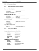
Environment Guide Version 10.00.00 KCS Fax over IP, pass-through mode Tested hardware: HP ProLiant DL380 G7, 12 CPUs x 2,665 GHz (X5650), 24 GB Memory, HP Smart Array P410i/1GB Tested software: VMware ESXi, 5.5.0, Build 1331820 Windows 2012 R2 Host with Hyper-V-Role Guest operating systems: Windows Server 2008 SP2 Standard 32-bit Windows Server 2008R2 Enterprise SP1 64-bit Windows Server 2012 64-bit Recommendations: Deactivate Hyperthreading 46 © Copyright Kofax.
Environment Guide Version 10.00.00 Under VMware assign or more unlimited CPUs and use processor affinity to assign physical CPU(s): Note: The affinity must be set on all virtual machines and all other machines must NOT use the processes assigned to the KCS FoIP VM in there affinity mask. E.g.
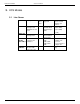
Environment Guide Version 10.00.00 Under Hyper-V assign unlimited and 100% reserved CPU(s): The maximum number of channels depends on the number of assigned CPU cores as shown in the table below: Number of Cores 1 48 Max. number of channels 10 © Copyright Kofax. All information is subject to change without notice.
Environment Guide Version 10.00.00 2 30 4 60 8 120 Notes: At least 2 cores should be reserved for optimum quality The values are valid for a hardware that is similar or better than the following reference system: HP Proliant DL380G8 (CPU Xeon E5-2640, dual 6-core, 2500MHz) The total CPU usage caused by other high priority processes/threads inside the VM that is used for KCS FoIP must be less thatn 20% from total available CPU usage. 5.5.
Environment Guide Version 10.00.00 3. VMware session under (GSX) server - version 1.0.2 39867 Single VM instance, installed on Win 2003 server with 3 GB physical RAM, 512 MB used for the VMware session 4. VMware session under VMware Workstation 5.
Environment Guide Version 10.00.00 Lincoln -2) TCIMG32 -2) VM WS VM GSX VM ESX PS 4 pages 7692 7543 7446 % 72 71 70 PCL 4 pages 9303 9490 10019 % 79 81 85 TIF 4 pages 26877 25723 27027 % 82 79 83 Mod. 300 10634 100 11742 100 32673 100 Pages/ hour - application started by TCDCLink Acrobat Standard 7.x script Office 2003 script VM WS VM GSX VM ESX PDF 4 pages 2884 2915 3346 % 84 85 97 Doc 2 pages 2419 2382 2829 % 42 41 49 Mod.
Environment Guide Version 10.00.00 Managing Hyper-V Hyper-V can be configured via the Hyper-V Manager (a Microsoft management console snap-in, part of administrative tools). For virtualization of KCS, the most important settings are in the sections Memory and Processor. Select a virtual machine and click Settings. Note: The values in the screen shots below are just an example. 52 © Copyright Kofax. All information is subject to change without notice.
Environment Guide Version 10.00.00 In the example above, one logical processor (2 GHz) is assigned to the virtual machine. The “Virtual machine reserve (percentage):” is set to 30 percent. Effectively, this machine has one processor (2 GHz) and 615 MHz are reserved for this virtual machine. The virtual machine was assigned 512 MB RAM. Supported KCS Components All KCS components supported on VMware are also supported on Hyper-V. For more information, see KCS Components Supported on Virtual Environment.
Environment Guide 5.7 Version 10.00.00 Restrictions From VMware only ESX Server is supported. VMware Workstation, VMware Player, and VMware Server (formerly called VMware GSX Server) are NOT supported. Hyper-V is only supported with Windows Server 2008 R2 or later as host operating system. A Tandem system can only be supported if the primary server is on another physical host than the secondary server. With TC/Archive, TC/Juke or a DVD/CD writer are not supported. Only network storage is supported.
Environment Guide 5.8.2 Version 10.00.00 Resource Bottlenecks Caused by Virus Scanners If there are several VMs running on a particular ESX server and there are any virus scanners installed on these VMs, these virus scanners should be set up so that they wouldn‟t start their virus check cycle at the same time.
Environment Guide Version 10.00.00 Disk usage: 5.9.1 Test Results: Three-Page Messages The TCOSS cache was set to the defaults: Registry key Value TCOSS/Drive0/DirCacheSize 2048 TCOSS/Drive0/DocCacheSize 40960 TCOSS/Drive0/DataBaseCacheSize 5120 This test run was done with messages of 3 pages, one short text page and 2 rather large image pages consisting of the CCITT fax test image. The outbound messages were put into TCOSS by two TC/LINKXML instances, 1 on the primary and 1 on the secondary master.
Environment Guide Version 10.00.00 The following values were measured with the Performance Monitor (on the primary system): Object Physical Disk Instance D: (TCOSS) TCOSS Cache Database Directory Document _Total TCOSS TCLINK TWS processes TCOSS Processor Process 5.9.2 Counter Disk Writes/sec Disk Write Bytes/sec Disk Reads/sec Disk Read Bytes/sec %Disk Write Time %Disk Read Time Cache Misses/sec Cache Misses/sec Cache Misses/sec % Processor Time (0 ..100) % Processor Time (0 ..
Environment Guide Version 10.00.00 TCOSS/Drive0/DataBaseCacheSize 51200 The test run was done with messages of 2 pages, both average image pages resulting from the input PDF attachment. The outbound messages were put into TCOSS by four TC/LINK-XML instances, 2 on the primary and 2 on the secondary master. Outbound message size in TCOSS was about 150,000 bytes (PDF attachments plus TCI alternative). The size of the received messages was about 135,000 bytes.
Environment Guide 5.9.3 Version 10.00.00 Test Results: Secondary Master Failure The error scenario of a secondary master failure was simulated by stopping the TCSRV service on the secondary master. The status agent was running during the tests. The secondary master was stopped for 10 minutes, the test loop continued running. There was no noticeable change in the performance of the primary master while it was running stand-alone, which means that the tandem operation did not slow down the test workload.
Environment Guide Version 10.00.00 Update kB/sec 848 Update Write kB/sec 216 TCOSS Cache Database Cache Misses/sec 1 Directory Cache Misses/sec 1 Document Cache Misses/sec 1.4 Processor _Total % Processor Time (0 ..100) 33 Process TCOSS % Processor Time (0 ..400) 32 The TCOSS performance counter “Update kB/sec” shows the amount of data read from the primary master, the performance counter “Update Write kB/sec” gives the amount written to the secondary master.
Environment Guide Version 10.00.00 %Disk Read Time 0.8 Read kB/sec 199 Reads/sec 16 Write kB/sec 595 Writes/sec 97 Update kB/sec 454 Update Write kB/sec 335 TCOSS Cache Database Cache Misses/sec 1.7 Directory Cache Misses/sec 1.4 Document Cache Misses/sec 13 Processor _Total % Processor Time (0 ..100) 31 Process TCOSS % Processor Time (0 ..400) 29 The additional disk writes caused by the update from the secondary master are seen in the TCOSS Disk performance counter “Update Write kB/sec”.
Environment Guide Version 10.00.00 With more than 1800 messages in the outbound queue cache misses went up: Object Physical Disk Counter Value Disk Writes/sec 103 Disk Write Bytes/sec 632,000 Disk Reads/sec 14.4 Disk Read Bytes/sec 187,000 %Disk Write Time 67 %Disk Read Time 6.3 TCOSS Cache Database Cache Misses/sec 0 Directory Cache Misses/sec 1.3 Document Cache Misses/sec 13.
Environment Guide Version 10.00.00 6. IPv6 Protocol 6.1 Introduction IPv6 protocol is the successor of the well-known IPv4 protocol which is being used in the Internet nowadays. It was defined in December 1998 by IETF in the specification RFC 2460. The necessity for better IP protocol is driven especially by the lack of address space provided by IPv4 addressing scheme.
Environment Guide 6.2.2 Version 10.00.00 IPv6 Address Types There are three types of IPv6 addresses: unicast, multicast and anycast. Unicast IPv6 address is an address for a single interface. Multicast IPv6 address is an address for a set of interfaces and a packet sent to such an address will be delivered to all interfaces identified by this address. Anycast IPv6 address is also an address for a set of interfaces, but a packet sent to such an address is delivered to one of these interfaces. 6.2.
Environment Guide Version 10.00.00 Having received the IPv6 address prefix from the router, IPv6 host generates its interface identifier in order to generate the full IPv6 address.
Environment Guide Version 10.00.00 The interface has the following IPv6 addresses assigned: 1.
Environment Guide 6.4.3 Version 10.00.00 Scenario 3: IPv6 only Network Having started to implement the Scenario 1 or 2, the final goal is clearly the IPv6 only network. All nodes in the networks which could be IPv6 enabled communicate via IPv6 only but they can„t reach IPv4 nodes which could not be equipped with IPv6 for any reason (old applications not supporting IPv6, old OS, running on the old hardware etc).
Environment Guide Version 10.00.00 KCSCore IPV6/IPV4 TC/LINK Server IPV6/IPV4 IPV6/IPV4 Network LS1 IPV4 EmailServer IPV4 KCSClient IPV4 KCSClient IPV6 In this way administrators may perform the migration towards IPv6 step by step, for example starting by IPv6 enabling of the servers, and then adding IPv6 for related client applications. 6.5.
Environment Guide Version 10.00.00 KCSCore IPV6 TC/LINK Server IPV6 IPV6 Main-Network IPV4 Sub-Network NAT-PT Translation EmailServer IPV6 LS1 IPV4 KCSClient IPV6 KCSClient IPV6 There are the following requirements to implement NAT-PT on a Cisco router in order to integrate KCS IPv6-only Windows applications with KCS IPv4-only hardware boxes: 1.
Environment Guide Version 10.00.00 1. In order to send a packet to the LS1, KCS core has to send it to its IPv6 “proxy address” FD96::1 (the IPv6 network must take care that this packet would be routed to the appropriate NAT-PT router‟s interface) 2. The router recognizes the prefix fd96::/96 in the packet‟s destination address and executes the NAT-PT translation for this packet (due to NAT-PT prefix configuration) 3.
Environment Guide Version 10.00.00 ipv6 nat v6v4 source fd96:eb5f:7508:5760:204:23ff:feac:4172 172.20.148.53 ipv6 nat prefix FD96::/96 ! Cisco router 28xx configuration using dynamic IPv4-mapped NAT-PT: This configuration allows each IPv6 only host to talk with any of the IPv4 only hosts by: 1. Defining the pool/range of IPv4 addresses as IPv4 “proxy” addresses for IPv6 hosts (in the example below 172.20.148.53 – 172.20.148.62 with the prefix length 24, which corresponds with IPv4 mask 255.255.255.0) 2.
Environment Guide Version 10.00.00 2. It may be necessary to disable IPv6 redirects on the IPv6 interface taking part in the NAT-PT by the command no ipv6 redirects (see examples above). The reason for this is unclear. However, with the dynamic NAT-PT configuration above without suppression of IPv6 redirects, the router very often (but not always) sent the ICMP6 redirect messages to IPv6 KCS core host and thus instructing it to sent its IPv6 packets to a different router which was completely wrong. 6.
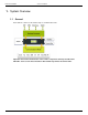
Environment Guide Version 10.00.00 7. Configuration Examples 7.1 How to Configure a KCS Solution The examples on the following pages show typical KCS hardware configurations. The optimum configuration for every single customer is planned by trained Kofax sales and technical professionals together with customer representatives. © Copyright Kofax. All information is subject to change without notice.
Environment Guide 7.1.1 Version 10.00.
Environment Guide 7.1.2 Version 10.00.00 FAX + VOICE via ISDN (BRI or PRI) line; FAX via Analogue (T/R or E&M) Line Entry Solution with Application Server Model 301 and KCS Models 304 and 305 7.1.3 TELEX and Host Connections Solution with Application Server Model 300 and KCS Model 202 LAN © Copyright Kofax. All information is subject to change without notice.
Environment Guide 7.1.4 Version 10.00.00 KCS Tandem Configuration Solution with 2 Application Servers and KCS Line Servers 76 © Copyright Kofax. All information is subject to change without notice.
Environment Guide © Copyright Kofax. All information is subject to change without notice. Version 10.00.
Environment Guide 7.2 Version 10.00.00 How to Estimate Bandwidth Requirements and Configuration Limits 7.2.1 Bandwidth Requirements Application Server and KCS Line Server are linked via a TCP/IP connection – either local 10/100Base/T or WAN connection in case of a BranchBox. Line Server Bandwidth Round Trip Time 30kBit/s per fax channel 70kBit/s per voice or mixed fax/voice channel 1000msec (256Byte block size) BranchBox Bandwidth Round Trip Time 30kBit/s per fax channel 1000msec max.
Environment Guide 7.3 Version 10.00.00 Upgrade Path, Legacy Hardware Upgrades should be exclusively done by technicians that are trained and certified by Kofax! 7.3.1 Upgrading from a Model 1xx/2xx/3xx to Model 305 or Third-Party Server Licensing Get new license keys for the new system. In urgent cases you may use the KCS test license keys.
Environment Guide Version 10.00.00 Follow instructions of the appropriate Hardware-Manual for component upgrades. This has to be done exclusively by trained Kofax technicians with components that are provided by Kofax and therefore have been tested for compatibility. 7.3.3 Software Upgrade Follow the instructions in the documentation of the relevant module. 7.4 How to Determine System Performance 7.4.
Environment Guide 7.4.2 Version 10.00.00 KCS HW-Requirement Calculator The KCS hardware requirement calculator is a Microsoft Excel sheet which determines the required hard disk speed from fax and link throughput figures and configuration options. The orange fields are input values. The white fields are calculated intermediate values, the result fields are blue.
Environment Guide Version 10.00.00 The 3 other input fields (“average message size in bytes”, “fax line usage per message in seconds” and “average number of pages”) have preset values which should be about right for an average installation. The “peak message throughput per hour” value is calculated from the “fax line usage per message in seconds” input value and the number of lines.
Environment Guide Version 10.00.00 The average 2009 desktop hard disk has seek times of 9 or 10 milliseconds, while a fast server-grade hard disk may show seek times of 2 to 4 milliseconds. The average latency (half a revolution) can be calculated from the rotational speed of the disk: RPM Average latency 5400 5.6 ms 7200 4.
Environment Guide Version 10.00.00 It‟s recommended to use RAID 1+0 (mirrored sets in a striped set). Also possible is RAID 0 for each half of a tandem system. RAID 5 is not recommended, it performs poorly on random writes. Example: A HW RAID 1+0 using a RAID controller with 512MB Battery-Backed Write Cache (BBWC) option and 8 hard disks with individual access times of 7 ms gives random write throughput figures of about 2000 writes per second.
Environment Guide Version 10.00.00 The above measurement was run on a system with hard disk write caching enabled. The first value reported is a bit higher as the cache fills up, this value can be discarded. With hard disk write caching disabled the same system showed these throughput numbers: Remember that hard disk write caching requires an uninterruptible power supply (UPS). Also do not forget to clean up the test file “C:TcDiskTest.bin” or “D:TcDiskTest.bin” after finishing the throughput tests. 7.
Environment Guide Version 10.00.00 TC/LINK-FI: Test Description Pages/hour Messages/hour T1. Text msg 1P Mail -> TC 13242,6 13242,6 T2. TCDC Word 1P Mail -> TC 429,6 429,6 T3. TCDC Word 100 P Mail -> TC 3546,8 35,5 T5. Bin Att (105K) Mail -> TC 4439,5 4439,5 T6. Bin Att (1.14M) Mail -> TC 37771,5 377,7 T7. FAX TIF 1P TC -> Mail 3096,8 3096,8 T8. FAX TCI 1P TC -> Mail 29580,9 29580,9 T8. FAX TCI 1P TC -> Mail 29173,4 29173,4 T9. Text msg 1P TC -> Mail 72000,0 72000,0 T10.
Environment Guide Version 10.00.00 TC/LINK-SC: Test Description Time measured (ms) Messages/hour T1. Text msg 1P Mail -> TC 4000 9000,0 T2. TCDC Word 1P Mail -> TC 75000 480,0 T3. TCDC Word 100 P Mail -> TC 320000 112,5 T5. Bin Att (105K) Mail -> TC 70000 514,3 T6. Bin Att (1.14M) Mail -> TC 290000 124,1 T7. FAX TIF 1P TC -> Mail 18000 2000,0 T8. FAX TCI 1P TC -> Mail 15000 2400,0 T9. Text msg 1P TC -> Mail 13000 2769,2 T10. Bin Att (105K) TC -> Mail 13000 2769,2 T11. Bin Att (1.
Environment Guide Version 10.00.00 The goal of the NIC teaming services is to provide fault tolerance across a team of two or more ports on a TCOSS server. By NIC teaming more than one physical NIC to a logical NIC, high availability of a TCOSS server is maximized. Even if one NIC (or cables) fails, the network connection does not cease and continues to operate on other NICs. 7.5.
Environment Guide Version 10.00.00 Click New Team to start a wizard that guides you through the process of creating a new team. Type a name. Select team members: Select team type: © Copyright Kofax. All information is subject to change without notice.
Environment Guide Version 10.00.00 When you finish the wizard, you can view and change the properties of the team: Network connections after defining a NIC team: 7.5.2 NIC Teaming with HP Networking Configuration Utility (NCU) On computers with HP network interface cards, you can define teaming with the HP Network Configuration Utility (NCU). This tool can be found from HP webpage: http://search.hp.com/query.
Environment Guide Version 10.00.00 The original state of network connections without NIC teaming: Start HP NCU. Select the members of NIC team. Click Team. Edit the properties of the team. Click OK, then click Save. The network connections will change: © Copyright Kofax. All information is subject to change without notice.
Environment Guide Version 10.00.00 If you need to configure the IP settings manually, open the local area connection properties of defined team. Note: Close HP NCU before opening properties. 92 © Copyright Kofax. All information is subject to change without notice.
Environment Guide Version 10.00.00 To display the state of team, open NCU, select the team and click Properties. © Copyright Kofax. All information is subject to change without notice.
Environment Guide Version 10.00.00 8. Operating and Maintaining the KCS System 8.1 Operation of Tandem Server System with Software Status Agent In general operation of the Software Status Agent is similar to the Status Box. For details see user manuals for TCMON. 8.1.1 Recommended Power On/Off Sequence for Tandem Server If possible, the following sequence should be used if a model 22x must be switched off or on manually. Turning off a TC means stopping TCOSS.
Environment Guide Version 10.00.00 2 ISDN BRI Channels running on second LS1 (Booted by Primary, Secondary can take over) Test 1: Primary Server Off – Secondary Server Takes Over The system is running in normal mode. The Primary Server has the control. The primary server gets powered off.
Environment Guide Version 10.00.00 Unavailable time 1:52. 8.1.3 Operation of Line Server Model 305 Front View of LINE SERVER Model 305 BRI 1 BRI 2 PRI 1 PRI 2 Mode LAN 1 LAN 2 Set 16x2 character LC-Display On the front side of LINE SERVER Model 305 there are connectors to BRI/PRI and LAN lines. Each plug has 2 LEDs that indicate Status and Activity as shown in the tables below. Please note that there are slight differences between the LEDs of LS1V1 and those of LS1V2.
Environment Guide Version 10.00.00 LED status Left off TC23.
Environment Guide Version 10.00.00 Line Server ONE 5/32 Lines OK Mode Mode DSP Status? 1 Select with Set Settings? 2 Select with Set Versions? 3 Select with Set Reboot? 4 Select with Set Set Set Set Set DSP0 Status 1-1 Active IP Address 10.11.2.27 2-1 Version Info 3-1 TCBios 2.00 Press Set to reboot Set DSP1 Status 1-2 Idle Netmask 2-2 255.255.255.0 Version Info 3-2 TCLinux 1.05 DSP2 Status 1-3 Not installed IP Gateway 10.0.0.1 Version Info 3-3 CS1: 1.00.
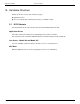
Environment Guide Version 10.00.00 Changes apply only after MODEL 305 is rebooted. You can reboot MODEL 305 from the Reboot menu (see below). Versions This menu displays version numbers of various software components of MODEL 305. Reboot When selecting reboot, you are asked to press set to confirm the choice. All ongoing activities are abandoned immediately. That implies that ongoing calls are interrupted.
Environment Guide Version 10.00.00 description 1 trace Information Describes situation that is caused be user activities or previous errors. 2 warning warning 3 line out of order error 4 HW/SW error corrected error Complete System is available now, but with reduced security or for restricted time. Any module detected an error. Any channel stopped working due to wrong configuration, insufficient license and line errors. Errors that should not occur but could be corrected (e.g.
Environment Guide 8.1.6 Version 10.00.00 Replacement of Interfaces Interfaces may be replaced exclusively by trained Kofax technicians. Line Servers can be switched off for maintenance and will reboot automatically after power on. 8.2 KCS Performance Counters Many KCS applications provide special performance counters that can be checked by applications like the Windows Performance Monitor. 8.2.
Environment Guide Version 10.00.
Environment Guide 8.2.4 Version 10.00.00 Language Support and Help Text KCS supports only English counter names, however if there are any other languages found (additional language sub-keys beside “009” below the registry key “HKLM\SOFTWARE\Microsoft\Windows NT\CurrentVersion\Perflib”) counter names for these will also be written to the counter initialization file with the English text. Similar there is no additional help text available, but the counter name will also be set as help text.
Environment Guide Version 10.00.00 Last Help DWORD - PerfIniFile STRING “TcLibPerf.ini” located here: “HKLM\SOFTWARE\Microsoft\Windows NT\CurrentVersion\Perflib\” The “First Counter” value is the offset to calculate the absolute counter index from the relative counter index in the counter ini-file.
Environment Guide 2) 8.2.7 Version 10.00.00 Stop all KCS applications by stopping TCSRV and also close TC/Mon; -> after that tclib32.dll should not be loaded any more by any application. You can check that e.g. with the tool “Process Explorer”. Local Perfmon instances are shown as process “mmc.exe”, remote connections use (on Windows 2003) the process “svchost.exe”.
Environment Guide Version 10.00.00 16) Counter initialization file 17) Trace files - location c:\tcoss\trace; from all KCS applications and from Perfmon (“TCLIBPERFx.trc”) 18) Registry export from: HKLM\SYSTEM\CurrentControlSet\Services\TcLib\Performance HKLM\SOFTWARE\Microsoft\Windows NT\CurrentVersion\Perflib HKLM\SOFTWARE\TOPCALL 8.3 Windows Error Reporting Some KCS link and server components are server applications that function without user interaction.
Environment Guide Version 10.00.00 9. Security Strategy No doubt there are no secure servers on the market but the level of security or defense measurement depend on the person who looks after the network environment. This chapter is not a security handbook. Neither is it a guarantee for a secure KCS server but it should help you to estimate the scale of raid for your system. 9.1 General By carelessness, wires often get plugged off or equipment gets switched off. (E.g.
Environment Guide Version 10.00.00 On the other hand, there are many KCS applications/modules communicating with or through third-party products (e.g. mail clients) where the TCP/UDP connectivity is not so straightforward (for example TC/Report – MS SQL server, or H.323 FoIP/VoIP integration), where one well-known TCP or UDP port is being used to establish the first connection through which further dynamic higher TCP or UDP ports to be used are agreed.
Environment Guide Version 10.00.00 TCECP LS1 TCPMeter TCUAS TCMON KCS Monitoring API TCMON KCS Monitoring API KCS Monitoring API (1) KCS 9.0(2) N N KCS 9.0 Y TCECP (Voice Server) connection with LS1 LS1 TCOSS TCSRV 5001/tcp 5002/tcp 5011/tcp 445/tcp 445/tcp Y N N TCPMeter connection with the LS1 TCUAS console with the TCOSS TCMON connection with the TCSRV service TCSRV 64385/tcp KCS 9.0 N TCSRV 64384/tcp KCS 9.
Environment Guide Version 10.00.00 TC/Player TC/Dialer (through TCE_REM, the “remote engine”) TCECP (Voice Server) 135/tcp Random high TCP ports N Y TC/Report (workstation fetch) KCS Monitoring API WMI Random high TCP ports KCS 9.0 Y At first a connection to MS-RPC endpoint mapper is established (port 135), which tells the client which ports to use for connecting to particular RPC service (random TCP ports ranging from 1024 to 5000) for details see Voice Platform Manual See also http://support.
Environment Guide 9.5 Version 10.00.00 Services Many services are installed on each Windows computer by default. The following list displays a summary of the services and network protocols needed/supported from KCS software.
Environment Guide Version 10.00.00 10. Encrypting File System and KCS Encrypting File System (EFS) is a Windows feature that can be used to encrypt specific files, folders, or drives. It protects confidential data from attackers with physical access to the computer. EFS can be used to encrypt the data files of KCS core (TCOSS) and TC/Archive. 10.1 Encrypting TCOSS 1) 112 Create a new Windows user, for example “KCS”. © Copyright Kofax. All information is subject to change without notice.
Environment Guide 2) Version 10.00.00 Assign the right “Log on as a service” to the new user. Note: Consider the following bug http://support.microsoft.com/kb/2411938/en-us 3) Grant the user full control permissions for the TCOSS file structure file, by default C:\TCOSS\Data\KCS File Structure.tcoss. © Copyright Kofax. All information is subject to change without notice.
Environment Guide 114 Version 10.00.00 4) Configure TCOSS to run as user “KCS” – create or edit the Windows registry values HKLM\SOFTWARE\Wow6432Node\TOPCALL\TCOSS\Domain, UserID, and Password appropriately. 5) Restart TCSRV. Using Task Manager, verify that TCOSS is running under the user “KCS”. 6) Stop TCOSS using KCS Monitor. 7) Log on to Windows as the user “KCS”. © Copyright Kofax. All information is subject to change without notice.
Environment Guide Version 10.00.00 8) Enable encryption for the TCOSS file structure. 9) Log off as “KCS”. Log back on as administrator and start TCSRV. You can verify the encryption state with either of the following methods: Use the command line tool “cipher”. © Copyright Kofax. All information is subject to change without notice.
Environment Guide Version 10.00.00 View the file properties > Advanced > Details. 10.2 Maintenance of Encrypted TCOSS TCDISK must be started with runas /user:kcs tcdisk. WCONFIG can be used without restriction, as long as Get / Install Locally is not required. To use Get / Install Locally, follow these steps: Stop TCOSS using KCS Monitor. Start TCOSS in server mode with runas /user:kcs “tcoss /t”. 116 © Copyright Kofax. All information is subject to change without notice.
Environment Guide Version 10.00.00 Start WCONFIG. You can now Get / Install Locally (but not via net). When you are done, stop the special TCOSS mode by pressing Ctrl+C. Start TCOSS normally using KCS Monitor. You can use other low-level TCOSS tools (for example tcdir, tccopy, tcdel) in the same way (tcoss /t). 10.3 Encrypting TC/Archive This procedure is very similar to section Encrypting TCOSS. 1) Create a new Windows user, for example “KCS”.
Environment Guide Version 10.00.00 “Deny log on locally” for the user KCS. After this change, it is no longer possible to log on to the computer as user KCS, or run any process interactively as this user. This also prevents the usage of TCOSS tools, such as TCDISK. 10.5 EFS Information EFS encrypts data with a random file encryption key (FEK). The FEK is stored encrypted with the public EFS key. The related certificate can be viewed in the Certificate store.
Environment Guide Version 10.00.00 11. Installation Requirements 11.1 Important Safety Instructions SAVE THESE INSTRUCTIONS See APPENDIX A for other languages! Read and understand all instructions! Follow all warnings and instructions marked on the product! Do not use this product near water or in a wet basement! Do not place that product on an unstable cart, stand, or table.
Environment Guide Version 10.00.00 Unplug this product from the wall outlet and refer servicing to qualified service personnel under the following conditions: When the power supply cord or plug is damaged or frayed. If liquid has been spilled into the product. If the product has been exposed to rain or water. If the product does not operate normally by following the operating instructions.
Environment Guide Version 10.00.00 11.2 Desktop Mounting The KCS cabinet requires a place with easy access, power supply and enough space for ventilation. At the rear must be enough room for cabling. At the left and right must be enough space for ventilation. Side distance Rear distance Attention: Leave 1HE of 19” rack free above the RAID cabinet (for cooling purposes)! © Copyright Kofax. All information is subject to change without notice.
Environment Guide Version 10.00.00 11.3 Rack Mounting The KCS Models 305 may be mounted in any 19” standard rack with cooling and minimum depth of 600mm. One KCS Model 305 requires 1HE (45mm / 1 ¾” height). Model 305, since it is quite small and light, is not intended to be mounted on sliding rails – simply screw it with the front screws to the vertical rack rails.
Environment Guide Version 10.00.00 11.5 Access Protection To guarantee 24-hour continuous operation you should place the KCS system at a place where unauthorized access is impossible. The power supply has to be protected from unintentional disconnection. 11.6 Dust Protection The room where the KCS system is placed should be free of dust and other air pollution (like normal office environment). 11.7 General It is recommended to use a separate power circuit or an uninterruptible power supply (UPS).
Environment Guide Version 10.00.00 12. KCS Licensing 12.1 Licensing General KCS software is protected by license keys. These keys are maintained in the KCS server. At the time of installation the KCS engineer enters all required licenses. Licenses: A license key is required in order to enable a specified number of instances of a program. All licenses are entered using the KCS Licensing Tool, LICENCES.EXE. 12.2 Licensing Modes Starting with version 7.46.00, TCOSS supports a new licensing mode.
Environment Guide Version 10.00.00 12.4 Link Licensing 12.4.1 Per User Link Licensing Some TC/Links are licensed per user, such as: TC/LINK-LN TC/LINK-MX 12.4.2 Business Application Integration Link Licensing TC/Link-SC, TC/Link-SC7 and TC/Link-AC use a special form of per instance Licensing. First of all you need a license for every workstation on which a TC/Link-SC is running. Then, for every 3 instances of TC/Link-SC which are running on the same workstation, you need one TC/Link-SC license.
Environment Guide 12.4.4 Version 10.00.00 Image Licenses Image licenses are licenses required for image conversion done by the links. The image types needing a license are: Postscript PCL GIF Every time a TC/Link does file conversion this action is registered on TCOSS. If a registration is already used for the workstation hosting the TC/Link, it will be used again. If there is no registration available, the conversion will not be done. 12.4.
Environment Guide 12.5.2 Version 10.00.00 Tandem Status Agent If TCOSS has been configured as a tandem system, the system will check if a tandem status agent license exists. Otherwise TCOSS will run in restricted mode (all channels stop). After the license if provided, TCOSS must be restarted to leave the restricted mode. 12.6 TC/Archive There is no difference if TC/Archive is running on TCOSS, KCS hardware of third-party hardware.
Environment Guide Version 10.00.00 During the test mode licenses.exe displays the end of the test mode phase instead of the “Switch to Testmode” button. 12.
Environment Guide Version 10.00.00 12.
Environment Guide 12.12.1 Version 10.00.00 System Failure All licenses that are calculated with the TCOSS CPU number are valid 14 days after a CPU number change (for a single server hardware change). For a tandem server where the secondary server temporarily is the master, the licenses are valid for 61 days. Only link server and archive server licenses are calculated with the local CPU number instead of the TCOSS CPU number.
Environment Guide Version 10.00.00 13. Appendix A CONSUMER INFORMATION AND FCC REQUIREMENTS This equipment complies with Part 68 of the FCC rules. On the rear side of this equipment is a label containing, among other information, the FCC registration number and Ringer Equivalence Number (REN) for this equipment. If requested, provide this information to your telephone company.
Environment Guide Version 10.00.00 14. Appendix B: KCS Approvals and Standards Conformance 14.1 Model 305 (All Components), Model 304 and 350 14.1.1 CE Safety Standards: EN 60950:2000 CB Scheme for IEC 60950:1999 UL 1459 third edition (pending), UL94V-0 EMC Standards: EN 55022+A1, EN55024+A1, EN61000-3-2, EN61000-3-3+A1 FCC CFR47 Part 15 Class A 14.1.2 Quality Standard ISO 9001 14.1.3 ISDN Basic Rate Modem Line Interface Module TC23 TBR3 14.1.
Environment Guide Version 10.00.00 UL 1459 third edition, UL 1950 third edition, CSA C22.2 No. 950 (No. 225-M90 for RAID and Model 202), UL94V-0 EMC Emission Standards: EN 55022, CISPR 22, FCC Part 15, Subpart B, Class A, EN 50081-1:1992, 60555 Parts 2 + 3 EMC Immunity Standards: EN 50082-1:1992 14.2.2 Quality Standard ISO 9001 14.2.
Environment Guide Version 10.00.00 ETS 300 063 Direct Dialing In ETS 300 064 14.2.7 ISDN Primary Rate Line Interface Board TC34 Protocols: E1, T1/PRI DSS1 (Euro-ISDN / NET3 / ETSI) AT&T (USA) PABX QSIG (ECMA) E1: · ETS 300 011 ISDN Primary Rate User-Network Interface Layer 1 spec. and test principles · ETS 300 046 ISDN Primary Rate Access - safety and protection T1: · ANSI T1.403 Network-to-Customer Installation - DS1 Metallic Interface · ANSI T1.
Environment Guide Version 10.00.00 15. Post Installation Checklist Post Installation Checklist 15.1 Goal Make sure that after a successful installation/ integration phase, the KCS system will work properly after years as well. Visit the customer 4 to 8 weeks after the installation has been finished. 15.
Environment Guide Version 10.00.00 16. Appendix C /GERMAN Safety Instructions translated to the native language of the country where the system will be installed. Sicherheitshinweise, unbedingt aufheben! Lesen Sie alle Hinweise, bis Sie sie verstehen! Befolgen Sie alle Hinweise und Warnungen am Gerät! Verwenden Sie das Gerät nicht in der Nähe von Wasser oder in einem feuchten Keller. Stellen Sie das Gerät nicht auf einen Wagen, Ständer oder Tisch, wenn diese keine ausreichende Stabilität aufweisen.
Environment Guide Version 10.00.00 Wenn das Gerät trotz Befolgen der Bedienungsanleitung (System Manual) nicht ordnungsgemäß funktioniert, benützen Sie nur jene Einstellmöglichkeiten, die in der Bedienungsanleitung angeführt sind, denn unsachgemäße Einstellung anderer Kontrollmöglichkeiten kann zur Zerstörung des Gerätes führen und verursacht oftmals einen unnötig hohen Aufwand für qualifiziertes Servicepersonal, um das Gerät wieder in Gang zu setzen.