Document Scanner 9500 with Image Manager Document Scanner 9500 without Image Manager Integrator’s Guide A-61124
1 Introduction This Integrator’s Guide contains information that applies to the following Document Scanners: • Kodak Digital Science ™ Document Scanner 9500 with the Kodak Digital Science Image Manager • Kodak Digital Science ™ Document Scanner 9500 without the Kodak Digital Science Image Manager These scanners are high-performance, high-resolution rotary scanners designed for medium- to high-volume digital capture of business documents.
About this guide This Integrator’s Guide provides the information need ed to use the Kodak Digital Science Document Scanner 9500 . You should be familiar with the operation of the scanner. If you are not, refer the Appendix B, Reference Materials for a complete listing of available publications. In addition to this information, the Integrator’s Guide contains the following chapters: 1-2 • Chapter 2, Scanning Concepts , provides an overview of the scanning process.
2 Scanning Concepts This chapter provides an overview of the scanning process , a discussion of error conditions, and two methods of fault recovery. Scanning documents Follow this sequence to scan documents : set up the scanner , enable scanning, initiate polling, feed documents, and disable scanning. Setup To set up the scanner: 1. Determine and select the mode (configuration) to be used for the current application.
Enable scanning The host must issue a SCSI Scan command (XX) to enable scanning before documents can be transported through the scanner. If scanning has not been enabled, the feeder and transport system will not turn on. Initiate polling Initiate host system polling of the scanner to ensure scanned document images are transferred from the image buffer to the host system. Polling should continue until scanning is disabled.
When an error occurs, the host will receive a SCSI Check Condition Status. This indicates to the host that there may be one current error and potentially one or more deferred errors. The host must follow a Check Condition Status with a SCSI Request Sense command. The Sense data will indicate the type of error that has occurred. To receive subsequent pending errors , the host must execute a SCSI Test Unit Ready command.
Fault recovery Fault recovery methods are required when unanticipated circumstances interrupt scanning, such as a document jam. The two methods described below meet the needs of most users. However, other methods may be used. IMPORTANT: Before beginning fault recovery, make sure all the images and headers have been transferred from the image buffer to the host system. Interactive/online method Use the Interactive/online method when your primary concern is that the database has no duplicate images.
3 Image Headers Image header contents This chapter provides an overview of the type of information generated during the scanning process, and how to retrieve images and headers. The scanner collects the following information for each document scanned: Document number (Sequential ID Number) The scanner assigns a unique Sequential ID Number to each document. This number may be initialized by the host computer using a scanner-unique command.
Image address The scanner assigns an image address to the scanned document. The image address is based upon the index format defined in the current operating mode and the document level assigned to the document. Refer to Appendix C , Assigning Image Addresses for additional information. Header flags The scanner records any flags that have been set for special consideration.
Bar code header information If the Bar Code Accessory is installed and enabled and a bar code is detected on the document, the decoded information is included in the image header.
Image header format The following table gives the position and the format of each piece of data placed in the image header: Offset 3-4 Set by Command Format Dynamic Data 7 ASCII-10 Sequential ID Number 27 ASCII-8 Image Size – 45 ASCII-2 Document Level – 54 ASCII-2 Mode 71 ASCII-8 Line Length – 95 ASCII-8 Page Length – 110 ASCII-9 (Alpha) Image Address - Fixed Field – 120 ASCII-10 Image Address - Level 3 Field – 131 ASCII-10 Image Address - Level 2 Field – 142 ASCII-1
NOTES: • The header created for a rear side image is identical to the header created for a front side image except for the literal value (bytes 0–6); Front # is replaced by Rear #. • Each piece of information collected during the scanning process is placed in an image header associated with the scanned document image (two-sided scanning produces two image headers and two images-per-document; one-per-side). • The image header consists of 512 bytes. The header format is identical for all modes.
Default Image Header Format 0 1 2 3 4 F r o n t 30 31 32 33 34 60 61 e 90 91 5 6 7 8 9 10 11 12 13 14 15 16 17 # 35 36 37 38 39 40 41 L e v e l 68 69 70 71 62 63 64 65 66 67 L e n g t h 92 93 94 95 96 97 42 99 44 45 46 47 = 72 = 98 43 73 74 75 76 77 18 19 20 21 22 23 L e n g t h 48 49 50 51 52 53 M o d e 78 79 80 81 82 83 84 P a g e 111 112 = 100 101 102 103 104 105 106 107 108 10
Retrieving images and headers Headers and images are transferred to the host system via the SCSI Read command. The data can be transferred in one of three forms: header only, image only, or compound image, i.e., header with image. To determine the form, set the transfer type within the SCSI Read command. The image can be read in one of two ways: • Read the header, then read the image. • Read the compound image . IMPORTANT: The header should always be read before the image.
Recommended retrieval methods The following examples illustrate how to retrieve image h eaders and images. To read compound images (image header with image) using packets: • Perform a SCSI Read asking for 64K bytes of compound data. • From the header, you find the image is 316,000 bytes long. Assuming the header is 512 bytes long, 65,024 bytes of image were obtained from the first read. That means there are still 250,976 bytes of image to be read.
4 Scanner — Host Communications This chapter provides an overview of the communication link between the scanner and the host system. Communications between the scanner and the host system occur across a SCSI bus. The SCSI interface supports two-way command/data communication between the scanner and the host system. The SCSI-2 command set is supported.
5 The SCSI Interface This chapter describes the SCSI interface used with the scanners. For complete information on the appropriate SCSI specification, refer to SCSI-2 Working Draft ANSI X. 131-198X, Revision 6, 10/29/88. SCSI overview The SCSI interface provides a means of communication between a maximum of eight computer and peripheral devices, giving the host computer independence within this system. As a result, tape drives, printers, optical disks, communications devices, etc.
SCSI interface signal lines The SCSI interface uses 18 signal lines: Select (SEL) Acknowledge (ACK) Attention (ATN) Reset (RST) Host Computer Initiator Busy (BSY) Data (DB(0)-DB(7)) Data Parity (DB(P)) Target Control/Data (C/D) Input/Output (I/O) Message (MSG) Request (REQ) Issuing SCSI commands There are seven steps or phases for issuing commands to the scanner or controller: Bus Free Arbitration Selection Command Data Status Message Bus Free phase — the SCSI bus is not being used by an initi
Arbitration phase — an essential phase in a multi-host environment with multiple initiators. In this phase, multiple initiators compete for control of the bus. Only one initiator can have control of the bus at a time. The initiator asserts the BSY signal, simultaneously this initiator outputs its own SCSI ID bit to the SCSI bus. The initiator with the highest SCSI ID will win the arbitration and assert the SEL (select) signal.
SCSI status responses In the SCSI communication mode, a function is considered incomplete until a valid status response is received from the other end of the SCSI link. There are three valid SCSI status responses: Status Response Code Meaning Good Status 00H The frame was successfully received and individual fields within the frame contained legal characters. Check Condition Status 02H A special condition occurred.
SCSI message responses Message Code Direction Function/Action SCSI Spec Ref Command Complete 00H scanner->host Scanner indicating the I/O Section 5.6.5 process is completed and a valid status has been sent. Initiator-Detected Error 05H host->scanner Scanner continues current I/O process. Abort 06H host->scanner Scanner terminates current Section 5.6.1 I/O process. Message Reject 07H host->scanner Scanner continues current I/O process. Section 5.6.
SCSI conformance 5-6 The scanner conforms to the SCSI specifications as follows: • Single-ended, 8-bit bus, Cable A, shielded connector (Alternative 2). Cable B is not supported. • Single-initiator (one host) is supported. Disconnect and Reselect are not supported. • Asynchronous maximum transfer rate of 1.2 M Bytes per second. • Linked commands and command queuing are not supported. • Programmable target ID dip switch is factory set to 1. • RST signal reset is only monitored.
SCSI commands This section lists the SCSI commands that the scanner supports. Information for each command includes: • Command format operation codes (op codes). • Section numbers to reference in the SCSI-2 Specifications. • Command block descriptor. • Command specifics (parameters).
Define Window Parameters command Command op code: 24H SCSI Specification: Section 14.2.1 Command block descriptor Bit Byte 7 6 5 4 0 3 2 1 0 Operation Code (24H) 1 Logical Unit Number Reserved 2 Reserved 3 Reserved 4 Reserved 5 Reserved 6 (MSB) Transfer Length 7 8 (LSB) 9 Vendor Unique Reserved Flag Link NOTE: For single-sided documents, a single Define Window Parameters command should be sent.
Define Window descriptor bytes Bit Byte 0 1 2 3 4 5 6 7 8 9 10 11 12 13 14 15 16 17 18 19 20 21 22 23 24 25 26 27 28 29 30 31 32 33 34...
Define Window Parameters data Descriptor * 5-10 Definition Window Identifier = SFFFFF00 S=Side (0-Front, 1-Rear) FFFFF=Mode (0-18) Auto =0 Auto windows not supported X Resolution =0 = 70 to 300 If zero, will default to 200 dpi Document Scanner 9500 Y Resolution = Defaults to X resolution Upper Left X † = 0 to 14400* 0 to 12 inches (0 to 304.8 mm) Upper Left Y † = 0 to 24000* 0 to 20 inches (0 to 508 mm) Width † = 0,96 to 14400* 0 or 0.08 to 12 inches (2 to 304.
Descriptor Bit Ordering Data = 0000H 0001H Definition Always scans left to right, top to bottom Data packing within a byte (bit ordering) is selectable: 0000H=msb/right;lsb/left 0001H=msb/left;lsb/right (default) Compression Type = 00H, 01H, 02H, 03H 00H = no compression 01H = TSS Group III, 1-dimensional 02H = TSS Group III, 2-dimensional 03H = TSS Group IV Compression Argument = 000 - 255 K-parameter value for TSS Group III, 2-Dimensional Image Enhancement Filter = 0, 2, 3 =1 0, 2, 3 = no filte
Get Window command Command op code: 25H SCSI Specification: Section 14.2.2 Command block descriptor Bit Byte 7 6 0 5 4 3 2 1 0 Operation Code (25H) 1 Logical Unit Number Reserved 2 Reserved 3 Reserved 4 Reserved 5 Window Identifier 6 Single (MSB) 7 Transfer Length 8 (LSB) 9 Vendor Unique Reserved Flag Link Get Window data Descriptor Data Single =0 Window descriptors are returned for the current mode with any temporary overrides and all 18 saved modes.
Get Window Parameters header data Descriptor Window Data Length Data = 54 882 1756 Definition The value is equal to the data header, not including the window data length (8 bytes) plus the number of windows multiplied by the window descriptor length single window = 46 bytes all windows/simplex = 874 bytes all windows/duplex = 1748 bytes Window Descriptor Length A-61124 March 1999 = 46 Length of a single window descriptor 5-13
Get Window descriptor bytes Bit/Byte 0 1 2 3 4 5 6 7 8 9 10 11 12 13 14 15 16 17 18 19 20 21 22 23 24 25 26 27 28 29 30 31 32 33 34..
Get Window Parameters data Descriptor Window Identifier Data = SFFFFF00 Auto X Resolution Y Resolution Upper Left X † Upper Left Y † Width † Length † Brightness Threshold Contrast Image Composition =0 = 70 to 300 = = 0 to 14400* = 0 to 24000* = 0,96 to 14400* = 0,96 to 36000* =0 = 0 to 255 = 0 to 255 = 00H, 01H Bits per Pixel Halftone Pattern =1 = 0 to 7** RIF = 0, 1 Padding Type Bit Ordering = 00H = 0000H 0001H Compression Type = 00H, 01H, 02H, 03H Compression Argument Image Enhancement Filter
Descriptor Noise Filter Data = 0, 1, 2 No Scan =0 =1 =0 =1 =0 =1 Border Reduction ‡ Skew Correction ‡ 5-16 Definition 0 = no filter 1 = remove lone pixels 2 = majority rule No scan off (scanning enabled) No scan on (scanning disabled) Border Reduction disabled Border Reduction enabled Skew Correction enabled Skew Correction disabled Status indicated is the requested state. If auto-cropping is enabled, Border Reduction is ignored. See the Y/X/Y/Z Command description.
Inquiry command Command op code: 12H SCSI Specification: Section 7.2.
Inquiry data Descriptor Data Definition Peripheral Qualifier 000b Peripheral Device 06H Scanner device Remove Medium 0b Not removable Device-Type Modifier 01H 02H Simplex (front only) Duplex (front and rear) ISO Version 0 No compliance claims ECMA Version 0 No compliance claims ANSI Version 2H ANSI X3.131 Asynchronous Event Notification Capability 0 Set by initiators only Response Data Format 2H ANSI X3.
Read command Command op code: 28H SCSI Specification: Section 14.2.
Release Unit command Command op code: 17H SCSI Specification: Section 14.2.6 Command block descriptor This command is not fully implemented. A Good Status will be returned if it is executed.
Request Sense command Command op code: 03H SCSI Specification: Section 7.2.
Request Sense data Descriptor 5-22 Data Definition Valid =1 Data is always valid Error Code = 70H = 71H Current Error Deferred Error Segment Number =0 Not used Filemark =0 Not valid EOM =0 Not valid ILI =0 =1 No Incorrect Length Incorrect Length Indicator is on Sense Key = 00H = 01H = 02H = 04H = 05H = 06H = 0BH = 0DH No Sense or Incorrect Length Recovered error Not ready Hardware error Illegal request Unit Attention Aborted Command Volume overflow (buffer overflow) Information Byte
Sense Key 0 5 5 5 5 5 5 5 5 Additional Sense Sense Qualifier Code 00 00 20 00 20 80 20 82 20 83 20 84 20 85 20 86 20 87 5 20 88 5 20 89 5 5 6 4 4 24 25 29 47 4C 00 00 00 00 00 Description No additional information Invalid command operation code Invalid scanner-unique command Invalid scanner-unique command — unknown error Invalid scanner-unique command — unknown command Scanner-unique command executed at wrong time Invalid scanner-unique command — bad data Invalid scanner-unique command — wrong mo
Reserve Unit command Command op code: 16H SCSI Specification: Section 14.2.6 Command block descriptor This command is not fully implemented. A Good Status will be returned if it is executed. Bit Byte 7 6 5 0 1 4 3 1 0 Operation Code (16H) Logical Unit Number 3rdPty Reserved 3 Reserved 4 Reserved Vendor Unique Reserved Third Party Device 2 5 2 Reserved Flag Link 1 0 Flag Link Scan command Command op code: 1BH SCSI Specification: Section 14.2.
Send command Send is required when executing scanner-unique commands. Command op code: 2AH SCSI Specification: Section 14.2.
Using the Send command for scannerunique commands Scanner-unique commands may be sent to the scanner during the Data Transfer phase of a SCSI Send command. IMPORTANT: The Transfer Type field must be set to 80H. The following tables illustrate how a scanner-unique DA command with a data field of 345.
Test Unit Ready command Command op code: 00H SCSI Specification: Section 7.2.
6 Scanner-unique Commands This chapter provides information about the scanner-unique commands used for communication and data exchange between the scanner and host system. Scanner-unique commands, which are used to establish or change the scanner configuration can be executed by sending a SCSI Send command (with the Transfer Type set to 80H) from the host system.
Command summary The following table provides a summary of all available scannerunique commands. Detailed descriptions of each command appear on the pages indicated.
There are three types of image processing commands: • X commands affect both front and rear scanning. • Y commands affect only front scanning. • Z commands affect only rear scanning. When using SCSI Send: For duplex scanners, all three types of commands may be used. For simplex scanners, only the Y command type may be used. When using SCSI Read: Use only the Y and Z command types.
Commands Each scanner-unique command is described in this section. The command descriptions appear in alphabetical order. AX/Y/Z Cropping/ Auto Cropping The AX/Y/Z command defines the scan window (cropping parameters) to be used for the current mode. Data Field xs3...xs0 Data Field xl3...x10 ys3...ys0 Command Field yl3...yl0 Description A X/Y/Z Value(s) xs3...xs0 Start location for left side of scanning window — ASCII 4 bytes 0000–1200** xl3...
BX/Y/Z — Scan resolution The BX/Y/Z command defines scanning resolution for the current mode. Data Field res Command Field B X/Y/Z Data Field Description res scan resolution in dots per inch Value(s) 70 to 300* * Values must be specified in increments of 10 dpi. If not, values will be rounded to the nearest 10 dpi by the scanner. NOTE: Leading zeros are not permitted. CX — Clear buffers The CX command resets the image buffer and initializes the Sequential ID Number to 1.
DX — No scan The DX command enables or disables scanning for the current mode. Data Field Command Field stat Data Field stat EX — Bit order D Description X Value(s) no scan off (scanning enabled) 0 no scan on (scanning disabled) 1 The EX command defines the bit order within a byte of image data.
FX/Y/Z — Compression The FX/Y/Z command defines the compression for the current mode. It allows the optional specification of a K-factor for Group III, two-dimensional compression. Data Field cmp K-factor (opt) Data Field cmp K-factor Command Field F X/Y/Z Description Value(s) uncompressed 0 Group III compression (one-dimensional) 1 Group III compression (two-dimensional) 2 Group IV compression 3 K-factor only has meaning when using Group III, two-dimensional compression.
GX — End of job The GX command initiates the scanner End of Job sequence. This sequence includes: • • • • turning off the feeder flushing the transport turning off the transport disabling scanning NOTE: The image buffer is not cleared. Data Field Command Field none HA — Set mode G X The HA command changes the current scanner configuration to the configuration defined by the specified application mode.
JA — Define mode The JA command alters the preprogrammed application mode by storing the current operating mode in its place. After the current operating mode has been stored as one of the 18 application modes, it can be selected in one of two ways: the operator can select it by entering function code F01 on the scanner operator control panel; or the scanner-unique Set Mode (HA) command may be used.
JA command Example 2: • Mode 4 is the current application mode.
KX/Y/Z — Scan contrast The KX/Y/Z command defines the contrast used for the current mode. NOTE: A contrast of 0 results in a fixed threshold. Data Field cont Data Field cont Command Field K Description X/Y/Z Value(s) scan contrast ranging from 0 (fixed thresholding) to 100 (fully adaptive) 0–100 NOTES: • Leading zeros are not permitted. • If multi-level screening is enabled (LX/Y/Z ≠ 0), this command is used to enable/disable Error Diffusion.
MX/Y/Z — Image enhancement filter The MX/Y/Z command selects an Image Enhancement filter for the current mode. Data Field filter Data Field filter NF — Level of next document M Description Value(s) 0 halftone removal 1 no filter (all pass) 2 no filter (all pass) 3 The NF command sets the document image level for the next scanned document.
SX/Y/Z — Reverse image The SX/Y/Z command changes the white/black polarity for the current mode. Data Field rev Data Field rev TX — Simplex/duplex status Command Field S Description X/Y/Z Value(s) white/0 black/1 0 white/1 black/0 1 The TX command directs a duplex scanner to scan either one or both sides of the document(s) for the current mode.
YX/Y/Z — Border Reduction If auto-cropping is off (see AX, Y, Z command), the Y command removes borders on sides of documents. Data Field Border Data Field Border Command Field Y Description X/Y/Z Value(s) Border Reduction disabled 0 Border Reduction enabled 1 NOTE: If auto-cropping is on, and this command is sent, the machine will store the last commanded state of the Y command. This state becomes effective if auto-cropping is turned off.
Scanner-unique command samples There are several ways to alter the default image processing parameters: • temporarily override an individual parameter • temporarily override a group of parameters • permanently change an individual parameter • permanently change a group of parameters Temporary individual parameter overrides are performed by sending a single scanner-unique command using a single SCSI Send command.
The following table illustrates how the use of a string of scannerunique commands can temporarily override current mode parameters: RESULT ACTION Compression Resolution Scanner is in Mode 1 3* 200* Host executes SCSI Send command with 2FX300BX 2 300 Host executes SCSI Send command with 4HA 3* 200* Host executes SCSI Send command with 1HA 3* 200* *Parameter default value.
Permanently changing a group of parameters A permanent change to a group of parameters is performed by temporarily overriding a group of parameters and then sending a scanner-unique Define Mode (JA) command to save the values to a specified mode.** The permanent parameter changes remain in effect until a SCSI or power-on reset occurs.
Recommended usage of scanner-unique commands The recommended method of downloading and saving image processing parameters, when using scanner-unique commands, is to use a SCSI Send command to transmit all desired parameter changes, and a Define Mode (JA) command to permanently store the parameter changes in a specified mode. This method significantly reduces SCSI overhead.
7 The Diagnostic Interface (J45/COIN3) This chapter describes the communications between the scanner and an RS-232 terminal, which may used to receive diagnostic information. Usage The diagnostic interface (also referred to as COIN3) may be used to receive diagnostic messages. This interface may be used as a diagnostic tool during product development and integration. The diagnostic port is labeled J45 on the rear panel of the scanner.
Appendix A Glossary Batch A number of documents to be scanned as a group. Bi-tonal image An unscreened image that consists of pixels which are either black or white (1 bit/pixel), as opposed to gray scale (screened) images which consist of pixels which are assigned a value based upon a range of gray shades. Calibration An operation that determines any system nonuniformity for which the scanner must compensate during scanning. The unit must be calibrated at least once a day or after power has been turned on.
Document image level Rank associated with a type of document. Up to four levels — Level 3, Level 2, Level 1, and Level 0 — can be used. The level can be set automatically using a Patch Reader accessory, manually by pressing the Footswitch, by pressing a Level key on the control panel, or by sending a scanner-unique Level of Next Document command. Error diffusion mode Compromised between binary thresholding and screening; used for documents containing both continuous tone photographic and text information.
Multilevel indexing A method of organizing documents in a structured manner when one type of document is associated with a particular level and another type of document is associated with another level of greater or lesser importance. For example, an insurance application with batches associated with Level 3, claims associated with Level 2, and claim attachments associated with Level 1. Noise Small dots or specks that appear in the background of an image.
Scaling Method used to obtain output resolutions other than the base resolution of the scanner . Can be done only from a higher resolution to a lower resolution . Scanner-unique command Allows the host computer and the scanner to communicate with each other. Scanner-unique commands must be in the format described in this manual. Screening Creates a pseudo gray-scale image and the electronic equivalent of the technique newspapers use to print pictures. Recommended for continuous tone photographic images.
Appendix B Reference Materials The following publications are available for the Kodak Digital Science Document Scanner 9500.
Appendix C Assigning Image Addresses An image address may contain up to 15 characters, consisting of a maximum of 12 digits and a maximum of 3 delimiters. You must define the following four fields: • Field A represents Level 1. Its value is incremented when a document is assigned Level 1. • Field B represents Level 2. Its value is incremented when a document is assigned Level 2. In addition, the value of Field A is reset to zero. • Field C represents Level 3.
• Three Level Offset Format Field A is defined as having a field length of zero. Field B is defined as having a field length greater than zero. Field C is defined as having a field length greater than zero. Fixed Field may be defined, if desired. Example: FFFFFF.CCC.BBB. • Three Level Format Field A is defined as having a field length greater than zero. Field B is defined as having a field length greater than zero. Field C is defined as having a field length greater than zero.
Appendix D Image Processing Parameter Defaults Image processing parameters Image processing parameters are fine-tuned during integration for each application/document type, with the goal of optimizing document image quality.
Table D-1 — Scanner 9500 with the Image Manager Default image processing parameters Parameter Command Modes 1,5,9, Modes 13,17 Modes 2,6,10 Modes 14,18 Modes 3,7,11,15 Modes 4,8 Modes 12,16 Scan (X & Y) Resolution BX/Y/Z 200 200 200 200 200 300 300 Cropping Parameters AX/Y/Z auto crop auto crop auto crop auto crop x start = 0 170 0 170 0 170 0 x length = 0 864 0 864 0 864 0 y start = 0 0 0 0 0 0 0 y length = 0 1104 0 1104 0 1104 0 Threshold JX/Y/Z 90
Table D-2 — Scanner 9500 Recommended Image processing parameters Noise Filter (LX/Y/Z) Image Enhancement Filter 62 (default) 2-level None On On 100-120 0 Any Off Off <100, >120 Not used Any–MultiLevel Pictorial Halftones* (standard IP enabled) 100-120 0 2-level Off Off <100, >120 Not used Halftone Removal Continuous tone* photographic) with text (7-point type or larger) (standard IP enabled) 100-120 >0 None Off Off (Error Diffusion) (Error Diffusion) Any–MultiLevel Document
Table D-3 — Scanner 9500 without the Image Manager Default image processing parameters Parameter Command Modes 1,5,9,13,17 Modes 2,6,10,14,18 Modes 3,7,11,15 Modes 4,8,12,16 Scan (X & Y) Resolution BX/Y/Z 200 200 200 300 Cropping Parameters AX/Y/Z x start = 170 170 170 170 x length = 864 864 864 864 y start = 0 0 0 0 y length = 1104 1104 1104 1104 Threshold JX/Y/Z 90 90 90 90 Contrast KX/Y/Z 62 62 62 62 Screen (Dither Pattern) LX/Y/Z 0 (2-level) 0 (2-level)
Appendix E Image Processing This appendix provides an overview of image processing capabilities which are controlled by the host computer using scanner-unique commands and guidelines for evaluating scanned images.
Image processing capabilities This section describes the standard capabilities of the scanner. Refer to the end of this section for information on how to use the Adaptive Threshold Processor accessory. Cropping Cropping is a method of capturing a portion of the total document being scanned. The host computer provides the scanner with the following information that defines which portion of the document is to be captured: • Left margin — the left-most point is 6 inches (152.
Compression Compression is used to reduce the number of bytes needed for scanned document images, thus saving storage space and/or transmission time. This is accomplished with special algorithms that use run-length encoding. The scanner allows one of three types of compression: • TSS Group III, one-dimensional • TSS Group III, two-dimensional • TSS Group IV NOTE: There are several standard options for Group III, onedimensional compression.
Contrast (without ATP) Contrast determines the ability of the scanner to detect subtle differences in gray levels. It is defined as a percentage, from 0 to 100%. A high contrast value will produce a scanned output of mostly blacks and whites (only large changes in gray levels are detected). A low contrast value will produce a scanned output of mostly midtones (more subtle change in gray levels are detected). It is recommended that a relatively high contrast value be used to optimize the quality of text.
Image enhancement filters Image Enhancement filters are used to optimize certain maximum characteristics. The following Image Enhancement filter options are available for the scanner/microimager 990 only. • No (all-pass) filter — used when no enhancement to an image is necessary. • Fine Line (high-pass) filter — used to accentuate the fine details of an image. This filter is typically used to enhance the detail of an image which contains small print (i.e., point type).
Mixed mode/Error diffusion Mixed mode/Error diffusion processing screens photographic areas of a document to simulate gray levels, yet sharpens the edges of text. It is recommended that mixed mode/error diffusion be used when a mix of text, graphs, pictures, and colors in the documents are being scanned. Mixed mode/Error diffusion is not directly selectable. It is the result of various image processing parameters being set at a specific value (or within a specific range of values).
Noise filter The scanner uses two types of Noise filters: Remove Lone Pixel and Majority Rule. Use the Noise filter to increase the compression ratio and improve the appearance of document images. • Remove Lone Pixel — reduces random noise on bi-tonal images by converting a single black pixel surrounded by white to white or by converting a single white pixel surrounded by black to black.
This is the same document, using the Remove Lone Pixel Noise filter to suppress the background noise: E-8 A-61122/A-61124 March 1999
Resolution The resolution of a scanned image is defined by the number of pixels-per-inch (also known as dots-per-inch or dpi) that are used to create the image. The scanner is capable of producing document images of varying resolutions. For example, if the desired resolution is 100 dpi, and the scanner uses a base resolution of 200 dpi and the desired (100 dpi) resolution is achieved by scaling down from 200 dpi. There is at least one base resolution for the scanner.
Screening/Dithering Screening (dithering) is a method used to simulate gray levels. Screening is expressed in terms of levels, ranging from 2-level to 64-level, with several levels in between. Screening is a process that groups neighboring pixels together into a super-pixel. The size of the super pixel is determined by the screening level chosen (i.e., when a 64-level screen is chosen, the super-pixel contains 64 pixels; the super-pixel is 8 pixels wide and 8 pixels high).
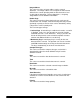
Thresholding Thresholding is used to convert a gray scale image into a bi-tonal (1 bit/pixel) image. The thresholding value ranges from 0 to 255. A low threshold value will produce a lighter image, and can be used to subdue backgrounds and subtle, unneeded information. A high threshold value will produce a darker image, and can be used to help pick up faint images. Refer to Chapter 6, Scanner-unique Commands for a description of the JX/Y/Z command.
This document was scanned using a (high) threshold value of 170: This document was scanned using a (low) threshold value of 85.
Adaptive Threshold Processor (ATP) accessory The Adaptive Threshold Processor separates the foreground information in an image (i.e., text, graphics, lines, etc.) from the background information (i.e., white paper background). The Adaptive Threshold Processor performs adaptive thresholding on gray scale scanned images and outputs a binary electronic image.
Image A was processed using a contrast value of 50. Image B was processed using a contrast value of 80. Compare the two images. Notice the word "four" in blocks 5, 6, 7 and 8 was not visible in Image A, but is visible in Image B. Thus, the increased contrast value provided more legible text.
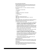
ATP Threshold settings The threshold parameter controls the lightness and darkness of the background in an image. Threshold can have a value between 0 and 255, with a default value of 90. As the threshold is increased, more of the darker grays in the image will become black. As the threshold is decreased, fewer of the darker grays will turn black. Image C was processed with default settings, and threshold set to 60. Image D was processed with the threshold set to 110.
Image Manager capabilities The Kodak Digital Science Image Manager accessory provides skew detection and correction, auto-cropping and border reduction. This accessory is not available on the Scanner/Microimager 990. Skew Detection and Correction The Image Manager provides skew detection and correction. Skew detection can detect up to a 45-degree skew and correct up to a 24-degree skew angle at 200 dpi or a 10-degree skew angle at 300 dpi.
Auto-cropping When auto-cropping is turned on, it detects and crops the borders of a document and outputs the actual size of the document that was scanned. The following illustrates how skew correction and auto-cropping work. Skewed document with auto-cropping and skew correction turned off Line Length = N x 16 pixels Same skewed document with auto-cropping and skew correction turned on Line Length = N x 16 pixels Areas filled with scanner background (16 pixels max.
The illustrations that follow show examples of skew correction in fixed cropping mode.
Example 3 If the entire image border is almost as dark as the scanner background (i.e., black or dark blue), deskew, auto-cropping and border reduction may not work properly. The resulting image will not be deskewed or auto-cropped, as shown in the example below.
Border reduction The border reduction feature only works when auto-cropping is turned off. Border reduction fills the area outside of the document edges with a white background within the fixed cropping width. The following illustration shows the effects of border reduction.
Evaluating scanned images This section describes methods for evaluating digitally scanned images. Evaluating scanned images requires an understanding of how scanned images are created and the types of source documents used to create these images. Image creation and source image types are also discussed in this chapter, as well as various evaluation criteria using a standard target as an example. Scanned images A scanned image is a digitized representation of a source image.
Computer-generated images Computer-generated images (printed by dot-matrix or laser printers) are discrete in both tone and space. Discrete in tone means the image consists of pixels on a grid. The number of bits-per-pixel determine the number of gray levels available. The spacing between points on the grid determine the resolution of the image. Fewer bits-per-pixel or large grid spacing reduce computer-generated image quality.
Evaluation criteria Target A-61122/A-61124 March 1999 The target used is the IEEE Std 167A01987 Facsimile Test Chart. This target was chosen for its text and photographic content, as well as the assortment of resolution targets.
Staircasing Staircasing is displayed when a detail on the scanned image switches from the scan line to the next line of the grid. This is the same degradation seen on computer-generated images and is most apparent on shallow slopes and soft curves. Staircasing can be minimized by scanning at higher resolutions (more dpi). One factor which can aggravate staircasing is skew. Unlike computer-generated images, scanned horizontal and vertical lines may not be square with the image.
Use of the Halftone Removal option lowers the resolution of the image so it is lower than the scan resolution. The associated loss in resolution may not be acceptable for all applications. Figures C and D illustrate the effect of Halftone Removal on the aliasing patterns. Figure C Figure D Figure C Bars at 10, 50, and 96 lines-per-inch (lpi), scanned at 200 dpi with Halftone Removal. Figure D 120 dpi screen, scanned at 200 dpi with Halftone Removal. NOTE: 1 lines-per-inch = 2 dots-per-inch.
When using a traditional microcopy chart, resolution is read as the smallest target that is clearly visible, with no line loss (all five lines present). 4.0 line pairs-per-millimeter is the last target with all five lines visible. Noise and dynamic range Noise in the scanned image will appear as random specks. These specks may be caused by actual noise in the original (dirt or mottled colors) or introduced by the scanner.
Brightness A-61122/A-61124 March 1999 Brightness indicates that calibration is functioning correctly and is directly affected by threshold. Loss in brightness in a scanned image may indicate a need to recalibrate the scanner or to alter threshold values. Brightness is measured, using the step wedge, by counting the number of black and white steps.
EASTMAN KODAK COMPANY Document Imaging Rochester, New York 14650 Kodak, Digital Science and the ds monogram symbol are trademarks of Eastman Kodak Company. Printed on recycled paper. A-61124 3/99 © Eastman Kodak Company, 1999 Printed in U.S.A.