
Use and Care Guide


OPERATING INSTRUCTIONS
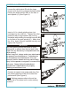
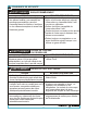
Push lever (F) forward and press down on the
trigger (E) to start the tool (A) (See Figure 1).
1
2
NOTE This tool features a power regulator valve.
Rotate the air regulator (D) until desired output is
achieved. The settings 1, 2, 3, 4 are only for
reference and do not indicate a specific power
output. “Setting 1” indicates the lowest speed
while “Setting 4” indicates the highest speed.
Rotate the air regulator (D) until the desired
setting lines up with marking on the outside
housing of the air inlet (J) (See Figure 2).
12
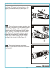
NOTE This tool also features an exhaust
deflector (I)
(See Figure 3).
that deflects exhaust air downward
3
J
4
3
3
1
2
3