
Use and Care Guide

26
OPERATING INSTRUCTIONS
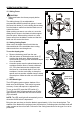
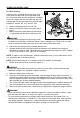
l. Before turning the saw on, perform a trial of the cutting operation by lowering the saw arm
to make sure that no problems will occur when the cut is made.
m. Hold the main handle (R), and use the On/Off switch (B) to turn the saw on. Allow several
seconds for the blade to reach maximum speed before cutting.
n. Slowly lower the blade into and through the work piece.
o. Release the On/Off switch. Allow the saw blade to stop rotating before raising the blade out
of the work piece.
CAUTION
• Always perform a “dry-run” cut to determine whether the operation being attempted is
possible before power is applied to the miter saw.
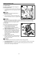
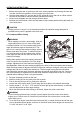
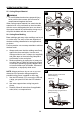
23. Compound Miter Cutting
WARNING
• When making a cut with a bevel angle, slide the
upper sliding fence (U) out of the cutting path.
A compound miter cut is a cut made using a miter
angle and a bevel angle at the same time. This
type of cut is used for decorative moldings, picture
frames, and other ne joinery. To make this type of
cut, the miter table must be rotated to the correct
miter angle and the saw arm must be tilted to the
correct bevel angle.
Always take special care when making compound
miter cuts, due to the interaction of the two angle
settings. Adjustments of miter and bevel settings are
interdependent. When the miter setting is adjusted, the effect of the bevel setting also changes.
When the bevel setting is adjusted, the effect of the miter setting is changed. It may take several
settings and trial cuts to obtain the desired cut. The rst angle setting should be checked
after setting the second angle, because adjusting the second angle affects the rst. Once the
two correct settings for a particular cut have been obtained, always make a test cut in scrap
material before making a nish cut in good material.
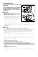
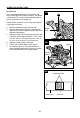
a. Remove the battery pack from the saw.
b. Mark the cutting line on the work piece with a pencil.
c. Pull out the arm-lock pin AC) to release the saw arm.
d. Loosen the miter-control lever (P) and rotate the miter table to the desired miter angle.
e. Quickly locate 0°, 15°, 22.5°, 31.6° and 45°left with right by the miter detents, or manually
lock the adjustment at other angle settings.
f. When the desired miter table setting is achieved, tighten the miter-control lever.
WARNING
• To avoid serious personal injury, always securely tighten the miter-control lever before
making a cut. Failure to do so could result in movement of the control arm or miter table
while making a cut.
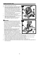
g. To set the bevel angle, rotate the bevel-lock knob (AA) to unlock the bevel and tilt the saw
arm to the desired bevel angle, as shown on the bevel scale. Bevel angles can be set from
0° to 48° left and 0° to 46° right.
23